
Related Manuals for Vivotek IP9165-LPC-A


Summary of Contents for Vivotek IP9165-LPC-A
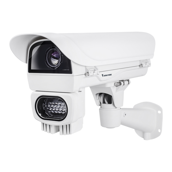
- Page 1 IP9165-LPC-A License Plate Capturing Solution (Street) Installation Guide Rev. 1.0 Document part no.: 625048300G Ordering part no.: IP9165-LPC-A (Street): 199004500G IP Sur veillance...
-
Page 2: Specifications
CAUTION: TO REDUCE RISK OF FIRE OR ELECTRIC SHOCK, DO NOT REMOVE COVER. NO USER SERVICEABLE PARTS INSIDE. REFER SERVICING TO QUALIFIED SERVICE PERSONNEL. UNPACKING: Unpack carefully. Electronic components can be damaged if improperly handled or dropped. If an item appears damaged in shipment, place it properly in its carton and notify the shipper. -
Page 3: Mounting Configuration & Dimensions
Mounting Configuration & Dimensions Swivel Positions and Directions 170 mm 415 mm 170 mm 502.8 mm 400 mm 400 mm 87.01 mm 135 mm 255 mm 105 mm USABLE USABLE AREA AREA AI-109 AE-23A 318 mm AE-21E 108 mm... -
Page 4: Component Description
Component Description Window frame Ventilation fan heater coil Ground VAIR module Camera Mounting Platform AC/DC or PoE Power distribution board M16 1/2" Waterproof cable glands Installation Suggestions If you plan to install this camera enclosure into a tropical, sea coastal, or an environment where salt water or corrosive industrial waste water/moist are present, please seal each stainless steel screws and fittings with a silicon grease compounds. -
Page 5: Installation
Installation Install the wall-mount bracket to a preferred location at your installation site. Drill mounting holes and a cable routing hole (if preferred) on a wall. Install the bracket. Prepare and route the wiring, Ethernet and 24V power source. Note that the AC 110V-to-24V power adapter should have a capcity of at least 4A. If you need to install an IR illuminator, remove the metal cover from the bottom of the housing using a T15 anti-tamper screwdriver. - Page 6 Orient and secure the IR illuminator to the housing using the 4 mounting holes at the bottom. Prepare power wires, a ground wire, and a CAT5e Ethernet cable. Pass them through the M16 waterproof connectors under the housing. Ethernet cable Ø4 ~ 6.5mm Power wires &...
- Page 7 Assemble the camera components, e.g., the CS ring and lens module. Secure the mounting plate to the bottom of the camera (the label side) using the included screw. There is a plastic mount pad in the package. You do not need the mounting pad using the VIVOTEK camera.
- Page 8 Adjust the camera's position so that the lens module can flush align with the tempered glass. Secure the camera using the screws and washers to the bottom of the housing. Lens flush w/ edge of enclosure Connect 24V power source to the power input terminal. Connect power wires from the DC 12V output to the camera.
- Page 9 You should prepare a power adaptor of the sufficient capacity for supplying 24V input. Below are the requirements: Total consumption Power adaptor LPC Street Connect the Ethernet cable to the camera's RJ45 socket. Also pass the combo cable of the IR illuminator through a waterproof connector. Connect the day/night signal lines from the housing to the DI/DO connectors on the camera's terminal block.
- Page 10 Configuring IR illuminator The following enclosures comes with adjustable IR lights: AE-23A Below are the parameters of the IR illuminator. Use the onboard jumpers to configure the beam angle for a different effective illumination range. VAIR no. of LEDs 18P/Dual Beam angle 10°...
- Page 11 Secure the intersection bracket to the bottom of the housing by driving two screws. Install the housing to the wall-mount bracket by aiming and pressing the spring mortise, and hook the bracket onto the groove in the spring mortise. Safety tether wire Secure the T30 anti-tamper screws on the other side using the included...
- Page 12 Secure the housing to the bracket by fasteninng 4 T30 screws. T30 x 4...
- Page 13 Adjust zoom and focus and open a web console with the camera to tune for the best image. When zoom and focus is done, Close the top cover and fasten the hex screws from below. Firmware configurable options: Make sure that the external IR is turned on in the night mode, and that the IR cut filter option is synchronized with the digital input you connected (default is DI1).
- Page 14 If using an iCS lens model, use the auto focus function for an optimal image. The configuration page automaticallly displays different options according to the lens you installed. iCS lens...
- Page 15 In the Configuration > Media > Image settings page, select an application scenario, LPC Highway, street, or parking lot mode. The related parameters, such as shutter time, will be automatically changed for the scenario. LPC-highway LPC-street LPC-parking lot If preferred, e.g., shooting fast moving vehicles, select the 60fps frame rate.
- Page 16 In the night mode, check if the input signals are correctly detected. You may simulate the night mode by blocking the IR unit's light sensor. Change the triggering parameters if necessary.
- Page 17 Appendix: RS485 Commands For housings that come with IR illuminators, wiper, and washer, commands can be delivered via the RS485 protocol. The RS485 connection uses the Pelco D protocol. Configuration parameters: Baud rate 2400 Data bits Parity None Stop bit Command format: Byte1 Byte2...
- Page 18 For example, IRmode_Auto FF 01 00 18 02 02 1D IRmode_DI FF 01 00 18 02 03 1E IRmode_CMD FF 01 00 18 02 04 1F LightSensorGate FF 01 00 18 03 LL CKSM When the IR Mode Light Sensor Auto, the Lux value to turn IR LED can be configured.
- Page 19 You can create custom command buttons by entering the Button name and the command itself: VaIR Lens Stop FF 01 00 00 00 00 01 VAIR Lens Wide FF 01 00 40 00 00 41 VaIR Lens Tele FF 01 00 20 00 00 21 Wiper On FF 01 00 09 00 01 0B Wiper Off...
- Page 20 This page is intentionally left blank.
Need help?
Do you have a question about the IP9165-LPC-A and is the answer not in the manual?
Questions and answers