Table of Contents
Advertisement
Quick Links
Advertisement
Table of Contents

Related Manuals for Grant Yoyolog


Summary of Contents for Grant Yoyolog
- Page 1 Yoyo Data Loggers Operating Manual...
- Page 2 The contents of this User Guide could be changed anytime without prior notice. Grant Instruments Ltd. disclaims liability for these changes. In using this software, Grant Instruments Ltd. takes no guarantee for any kind of dam- ages including all direct or indirect damages resulting from body injury, profit loss, op- eration interruptions, information / data loss etc.
-
Page 3: Table Of Contents
Grant Instruments Contents Contents ....................3 Hardware Checklist ................5 Quickstart ....................6 General information ................7 Installing the batteries ................... 8 Installation of YoyoView ................9 Main Software-Menu ................10 Preferences and general setup ..............10 Search for Devices ..................11 Logger Identification ................ - Page 4 Grant Instruments Logger Setup – Configuring Alarms ............30 Display logged data as a graph..............31 Display logged data as a table ..............31 Exit ......................31 Troubleshooting .................. 32 Understanding the LEDs ..............34 30641 V1.3 Yoyolog Page 4...
-
Page 5: Hardware Checklist
Grant Instruments Hardware Checklist Included in delivery for all loggers are: Data logger series yoyolog Lithium battery type CR2477N USB cable YoyoView Software for Windows supplied on USB-Stick Additionally included in delivery of YL-M32, YL-M41, YL-M42, YL-M90 YY-CS cable(s) Further options include:... -
Page 6: Quickstart
Grant Instruments Quickstart Receive readings in only six easy steps: ►Install the USB driver from the USB stick: execute file: …\USBDriver\USBXpressInstaller.exe ►Install YoyoView for Windows Execute file …\setup.exe ► Open the logger by unscrewing its rear cap. Insert the battery. Connect the USB cable to the respective ports of the logger and the PC. -
Page 7: General Information
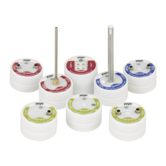
Grant Instruments General information The yoyolog series consists of a large variety of loggers: Some have an internal sensor only. Others have inputs for external sensors, whilst some have both sensor types. A full list of models can be found on our website. -
Page 8: Installing The Batteries
Grant Instruments Installing the batteries The logger’s power supply is provided by a 3.0V lithium battery (CR2477N). Optionally for high-temp-applications a CR2450HT battery can be supplied. The device offers internal battery monitoring. YoyoView will indicate when the battery will require replacing. In addition, the LED flashing periodically indicates the need for the battery to be replaced (see chapter 0, understanding LEDs for further information). -
Page 9: Installation Of Yoyoview
Grant Instruments Installation of YoyoView System requirements Hard-/Software Minimum-Configuration Recommended Configuration Computer: Intel Pentium, 1 GHz Intel Pentium III, 2 GHz Operating system: Windows XP/Win7 Windows XP/Win7 RAM: 512 MB 1 GB or more Monitor: Any windows-supported monitor Monitor with... -
Page 10: Main Software-Menu
Grant Instruments Main Software-Menu Preferences and Exit YoyoView Display logged data general setup as a graph Display logged data Search for devices as a table connected to the PC Preferences and general setup To set up preferences for the YoyoView Software, click on Preferences/Program or the Preferences icon. -
Page 11: Search For Devices
Grant Instruments Search for Devices Locate the USB port of the logger, next to the battery, and plug in the USB cable supplied with the logger. Plug the other end of the USB cable into any USB port on the PC. -
Page 12: Logger Identification
Grant Instruments Logger Identification By moving the mouse pointer across a picture of a logger, a prompt will appear to click once or twice on that picture. By clicking once, further information will appear to identify the logger. A serial number, the Short ID, Date Code, Description as well as the manufacturers name will be displayed. - Page 13 Grant Instruments The full serial number, logger status, number of channels, firmware version, battery capacity, memory percentage used and the actual logger time will be displayed. Logger Status gives information about the status of the logger. If the status is “sleeping”, no readings are being taken and the logger is waiting to be ‘set’...
-
Page 14: Logger Control
Grant Instruments Logger Control Once the logger has been selected, right click to enter the menu to control the logger. A logger control window is opened and will show the following functions Metermode, Start/Stop Logger, Download Data and Logger Setup. -
Page 15: Start/Stop Logger
Grant Instruments Start/stop logger Clicking on Start Logger in the logger control window will bring up the settings for logging. Note: that if the logger is already logging data, the Start Logger command will not be available. Instead the Stop Logger command will be displayed. - Page 16 Grant Instruments In the Start Datalogger window, the Stop condition for the logger can be set. If the Memory full option is selected the loggers will stop logging when the memory is full. If never (cont mode) option is selected the logger will start to overwrite the oldest readings when the memory is full.
-
Page 17: Download Data
Grant Instruments Download Data Clicking on Download Data will transfer all stored data to your PC. It will automatically store the files as a *.BIN-File and as a*.ASCII file. The original *.BIN-File is a compressed datafile which can be archived using a minimum of hard disk space. -
Page 18: Logger Setup - General
Grant Instruments Logger Setup - General Click on Logger Setup, to define general settings for the logger, i.e. channel settings, alarm settings). A picture of the logger is displayed so the inputs/slots can be identified. The battery capacity is displayed in the same picture. If the battery status is “green”... -
Page 19: Logger Setup - Sensor Slots
Grant Instruments Logger Setup – Sensor Slots Those loggers that have additional inputs for external signals or sensors have to be configured correctly to show the expected values and prevent damage. The input types that can be configured for different sensor/signals types are shown in the table: 30641 V1.3... - Page 20 Grant Instruments Click on Logger Setup, to configure the inputs. The actual configuration of the logger and the range are displayed. Click on the Sensor Slots tab. NOTE: This function is only available when the logger is not logging. Click on the symbol of the slot to be modified for example Slot2.
- Page 21 Grant Instruments YoYoView automatically assigns the minimum and maximum values of the sensor range. This can be altered if required. In order to set engineering units for the sensor, select Change to new Unit in the section SensorRange. Further settings can be entered. The above example shows the values for a sensor with a linear range of 0…50m/s = to 0…1V.
-
Page 22: Temperature Pt100/Pt1000/Thermistor
Grant Instruments 7.5.1 Temperature PT100/PT1000/Thermistor The standard temperature sensors supplied (YS-EU, YS-CM etc) are all PT1000- sensors. If you are connecting a standard sensor, select type Temp.PT1000. If you are using a sensor purchased elsewhere, assign pins 1 to 4 and select the appropriate sensor type in the software. -
Page 23: Sensors For Condensation
Grant Instruments 7.5.4 Sensors for condensation The condensation sensor Type SHS delivers a “1“ Signal when condensation has been detected and a “0“, if no condensation is detected. This connection can be configured in LoggerSetup/SensorSlot - SlotMode: Condensation [ ]. -
Page 24: Pulse Count - Voltage Signals >3V
Grant Instruments Important: Connecting voltages higher than 3 Volts will damage the device. 7.5.7 Pulse Count - Voltage signals >3Volts If the loggers YL-M41/42 and YL-M90 are used for pulse counts with a signal between 3V and 24V the YY-CP connection cable will be required. Operation with other cables may cause damage. -
Page 25: Strain Gauge - Sensors (Yl-M32 Only)
Grant Instruments Voltage DVM [mV]. The power supply for additional transmitters needs to be provided externally. Important: Connecting voltages higher than 10 Volts will damage the device. 7.5.9 Strain gauge – sensors (YL-M32 only) The YL-M32 logger can measure two strain gauges. It is designed for full resistance bridges at 60-700 Ohms. -
Page 26: Lowest-Voltage Measurement (Yl-M32 Only)
Grant Instruments 7.5.10 Lowest-voltage measurement (YL-M32 only) The YL-M32 can measure very low voltage signals for example in the range of +/-5mV with a resolution as low as 0,15µV. Microvoltage +V out-White GND Blue YY-CU This connection can be configured in LoggerSetup/SensorSlot - SlotMode: High-Impedance. -
Page 27: Current Measurement (Max 24 Ma)
Grant Instruments 7.5.12 Current measurement (max 24 mA) Current measurements can be made with signals up to a maximum of 24 mA. The signals need to be connected with the YY-CI cable. Input with another cable will cause damage to the device. -
Page 28: Soil Moisture Sensor - Decagon Series (Yl-M90 Only)
Grant Instruments 7.5.13 Soil moisture sensor - Decagon series (YL-M90 only) The ECH2O probes can be connected to the YL-M90 for measuring soil moisture. The sensors of the ECH2O series are capacitive sensors for soil moisture that measure the permittivity of soil. An output signal proportional to the soil moisture is created by altering the sensor’s reference voltage. - Page 29 Grant Instruments Installing the EC-5 1. The EC-5’s installation is especially easy to manage. After digging a sufficiently deep hole for the sensor, insert the brackets into unspoiled soil at the bottom or side of the hole. The sensor needs to be entirely covered, including the rubber over molding.
-
Page 30: Logger Setup - Configuring Alarms
Grant Instruments Logger Setup – Configuring Alarms Yoyo loggers have integrated alarm functionality. An LED will start to flash if thresholds are exceeded. Click on Alarm, to display the alarm settings. Then click on the symbol of the channel in order to change the settings. -
Page 31: Display Logged Data As A Graph
Grant Instruments Display logged data as a graph Click here or go to Data/Graph to display readings as a graph. Select the file to be graphed. YoyoView automatically searches its predefined folder: C:\Users\Public\Public Documents\Graphtool. As soon as the data has been fully processed the GraphTool-Software will pop up. -
Page 32: Troubleshooting
Grant Instruments Troubleshooting Typical error messages that may occur during operation are listed below. Try to solve the problem with the following help list before contacting your distributor. A) No logger is displayed First, check if the logger cable is correctly connected to the USB Port and to the logger. - Page 33 Grant Instruments Important notes for measuring humidity The Yoyo humidity/temperature probes are a precise, reliable humidity sensor element which has a good long-term stability. The capacitive sensor allows for humidity measurement in many applications and will give stable readings in clean environments for several years.
-
Page 34: Understanding The Leds
Grant Instruments Understanding the LEDs The logger LED’s for Type YL-T10 and YL-RH20 are coloured differently compared to those of the rest of the yoyo logger series. Datalogger YL-T10 , YL-RH20 Logger Status Red LED Yellow LED Green LED Logs at interval... - Page 35 Manufacturer´s Declaration of Conformity Grant Instruments (Camebridge) Ltd. does declare that, to the best of it knowledge and belief, the products referenced below meet the essential requirements and are in conformity with the relevant EC Directive(s) listed using the relevant section of the EC Standard.
- Page 36 Grant Instruments (Cambridge) Ltd Shepreth Cambridgeshire SG8 6GB...