Advertisement
Quick Links
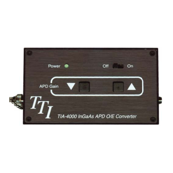
Optical to Electrical Converter
T
I
A
4
0
0
-2
-4
0
-6
-8
-10
0
1
2
T
he TIA-4000 is comprised of a fi ber coupled InGaAs APD detector combined with a variable reverse bias
voltage network and fast transimpedance amplifi er. The output of the unit brought out to a type K female
SMA connector. Light falling on the detector generates a positive-going proportional current. This current,
multiplied by the transimpedance produces a voltage that is proportional to the light incident on the detector
surface.
Normally the unit is used to drive a coaxial cable, this cable should have a 50 ohm characteristic impedance
and be terminated with a 50 ohm load at the oscilloscope or other measuring device to be used.
The active area of the TIA-4000 is 30 microns in diameter. It is coupled to a single mode optical fi ber. Typical
optical return loss is 52 dB and is caused primarily by the FC/APC connector employed.
The applied bias voltage controls the gain of the APD. This voltage in turn, is controlled by means of the two
push buttons on the top panel. The rightmost button increases the gain and the leftmost button decreases the
gain. There are 64 discrete gain settings that are retained in non-volatile memory when the power is turned off.
Thus the gain setting will be retained even though power is disconnected from the unit.
Pressing a button once causes the unit to advance in the selected direction by one step. Holding the button
down causes the unit to advance automatically until a limit is reached.
Operation Notes:
1: To avoid damaging the detector, the gain must be set to the lowest setting prior to turning off the TIA-4000.
2: Do not apply optical power to the detector until AFTER the device is power on and the APD bais is confi rmed
to be set to the lowest level.
TIA Freq. Response
3
4
5
6
7
8
9
10
GHz
Features:
• Wavelength Response 950 nm to 1650 nm
• Low Noise, High Gain
• Gain Settings from 2 to 7
• Bandwidth 30 KHz to 7 GHz typical
• SMA type K Output Electrical Connector
• FC/APC Style Fiber Optic Input Connector
Terahertz Technologies Inc.
169 Clear Rd, Oriskany NY 13424
Phone: 315-736-3642 Fax: 315-736-4078
Made In the USA
855-TTI-TEAM (884-8326)
email: sales@teratec.us
web: www.teratec.us
©10/2014 Terahertz Technologies Inc.
Advertisement

Related Manuals for TTI TIA-4000

Summary of Contents for TTI TIA-4000
- Page 1 50 ohm load at the oscilloscope or other measuring device to be used. The active area of the TIA-4000 is 30 microns in diameter. It is coupled to a single mode optical fi ber. Typical optical return loss is 52 dB and is caused primarily by the FC/APC connector employed.
- Page 2 Standard Warranty Two Years, Workmanship, 30 DaySatisfaction Guarantee Accessories Supplied Transit Case, Universal Power Supply, Manual TTI reserves the right to change specifi cations without notice. Operating Sequence Turn on sequence: Turn on the TIA-4000 Hold ▼ button for 7 seconds to decrease APD...
Need help?
Do you have a question about the TIA-4000 and is the answer not in the manual?
Questions and answers