Advertisement
Quick Links
Advertisement

Related Manuals for IRTrans IRTrans WiFi


Summary of Contents for IRTrans IRTrans WiFi
- Page 1 Manual IRTrans WiFi Version 1.01...
-
Page 2: Eu Declaration Of Conformity
Electromagnetic Compatibility as defined in DIN EN 55024 : 1998 + A1: 2001 + A2: 2003 DIN EN 55022 : 1998 limit class B + A1 : 2000 + A2 : 2003 Manual IRTrans System © 2012 IRTrans GmbH... -
Page 3: Initial Configuration
Installation LINUX: The LINUX SW can also be found on the IRTrans CD and on our website. It needs a JRE version >= 1.6. Connect the IRTrans WiFi to a suitable power supply (8-16V DC / >= 300mA) and with the supplied USB Cable to the computer. Now the USB Driver will be loaded automatically. -
Page 4: Troubleshooting
We therefore recommend not using the NTP setting. 12. Once the settings have been stored the IRTrans WiFi will connect to the WLAN. During that process the WLAN Status LED will blink green and red multiple times Once the device is connected to the WLAN the Status LED will be green. -
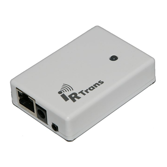
Page 5: Hardware Description
IRTrans Manual Hardware/Setup WiFi Version 1.01 Hardware Description Mini USB Connector Power connector (8-16V DC / >= 300mA / Center + / 5.0 - 2.1mm) RS232 Connector / 2 IR Output (Optional) WLAN Status LED (see below) IR Output (combined with 2 IR Output for RS232 + 2 IR;... - Page 6 IRTrans Manual Hardware/Setup WiFi Version 1.01 The red circle marks the jumper for the external High power transmitter. The other jumpers are used to configure additional hardware options (RS232 port, 2 Output). Those jumpers are set by factory and shall not be changed. Just setting the jumpers will not enable the HW options.
- Page 7 IRTrans WiFi Web Interface Once the device can be reached in the WiFi network all further configuration can also be done using the integrated Web interface. Of course the IRTrans SW via USB or WiFi can also be used for all configuration tasks.
- Page 8 – otherwise the irserver will not receive IR codes from this IRTrans module. The UDP Broadcast fields are only used for modules with integrated IR Database. They...
- Page 9 IR database. This function can, for example, be used to communicate with a Gira Homeserver™. The IR parameters can either be configured using the IRTrans GUI client or via the webpage “IR Configuration”. All the fields and their meanings are explained in detail in the User’s manual for the IRTrans...
- Page 10 IRTrans Manual Hardware/Setup WiFi Version 1.01 If the IRTrans WiFi module has got the optional RS232 port the RS232 dialog can be used to configure the RS232 settings. The password used to login into the web configuration front end can be changed in the “Change Password”...
- Page 11 (e.g. 20 43 0D 0A). This string will be send via UDP when the selected command is received. In the ASCII mode Carriage Return and Linefeed can be generated using “\r” and “\n”. Relay Control is not used with the IRTrans WiFi.
- Page 12 The integrated IR database (optional) allows using the IRTrans modules with different clients without the IRTrans server SW. To allow this, parts of the irserver software have been integrated into the Firmware of the IRTrans WiFi modules. However, due to restricted resources when using a Microcontroller it is not possible to implement the whole irserver with some 1.000 lines of code.
- Page 13 IP address of the WiFi module. When starting the IRTrans GUI client (irremote.exe) the IP address can be used as a parameter (e.g. “irremote 192.168.0.32“). Up to 4 clients can connect to a single IRTrans module. In addition multiple servers can use a single IRTrans WiFi module.
- Page 14 IRTrans Manual Hardware/Setup WiFi Version 1.01 IRTrans HTTP Interface. The HTTP Interface allows sending IR Codes stored in the IR Database using an HTTP / browser interface. Sending is done using a simple HTTP URL: http://192.168.0.32/send.htm?remote=<remote>&command=<command> The following parameters are supported: remote=<remote>...
- Page 15 IRTrans Manual Hardware/Setup WiFi Version 1.01 Declaration of Conformity According to 47CFR, Parts 2 and 15 for Peripherals Power Supplies used with Class B Personal Computers: IRTrans GmbH Located at: Einsteinstrasse 14, 85716 Unterschleissheim, Germany Declare under sole responsibility that the product identified herein, complies with 47CFR Parts 2 and 15 of the FCC rules as a Class B digital device.
Need help?
Do you have a question about the IRTrans WiFi and is the answer not in the manual?
Questions and answers