Table of Contents
Advertisement
Quick Links
Advertisement
Table of Contents

Related Manuals for Ouster OS2


Summary of Contents for Ouster OS2
- Page 1 OS2 Hardware User Manual For Rev-05 OS2 Sensors Ouster Sep 27, 2021...
-
Page 2: Table Of Contents
8.3 Configuring the Ouster Sensor ........ -
Page 3: Important Safety Information
1 Important Safety Information 1.1 Safety & Legal Notices The OS2-128, OS2-64, and OS2-32 have been evaluated to be Class 1 laser products per 60825-1: 2014 (Ed. 3) and operate in the 865nm band. L’OS2-128, l’OS2-64, et l’OS2-32 répondent aux critères des produits laser de classe 1, selon la norme IEC 60825-1: 2014 (3ème édition) et émettent dans le domaine de l’infrarouge, à... - Page 4 Use of controls, or adjustments, or performance of procedures other than those specified herein, may result in hazardous radiation exposure. Use of the OS2 is subject to the Terms of Sale that you agreed and signed with Ouster or your distributor/integrator. Included in these terms are the prohibitions of:...
- Page 5 Sensor Components. Electromagnetic Compatibility: The OS2 is an FCC 47 CfR 15 Subpart B device. This device complies with part 15 of the FCC Rules. Operation is subject to the following conditions: (1) This device may not cause harmful interference, and (2) this device must accept any interference received, including interference that may cause undesired operation.
-
Page 6: Proper Assembly, Maintenance And Safe Use
When the sensor is running, and the laser is operating, a faint red flickering light may be seen behind the optical window. Note that the OS2 utilizes an 865nm infrared laser that is only dimly discernible to the naked eye. The sensor is fully Class 1 eye safe, though Ouster strongly recommends against peering into the optical window at close range while the sensor is operating. -
Page 7: Sensor
For the purposes of this document, the term “OS2” refers to the family of sensors, and only where there is a difference in performance will each model be referred to by its specific model designation. -
Page 8: Mechanical Interface
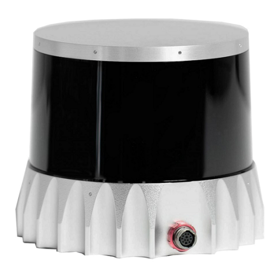
RJ45 cable (1 meter) Baseplate Mount Figure3.1: Sensor Components Downloadable CAD files for the OS2 can be found online at Ouster Download Page Warning: The water ingress protection rating for the sensor is only valid if the I/O cable is plugged into the panel mount connector on the base of the sensor, and the locking collet rotated past the détente click to the properly locked condition i.e past the détente position. -
Page 9: Mounting Guidelines
The shape of any heatsink should maximize the surface area for free and forced convection while being thick enough to allow the heat to conduct through the material. If you have questions about your specific mounting situation please contact the Ouster at sup-... -
Page 10: Operating Temperatures
4.1 Power Supply and Operating Voltage The OS2 Rev 05 Sensors are meant to operate at 12V and 24V nominal input voltage. A low voltage warning will be triggered if the voltage at the sensor connector drops below 9.5V. The sensor will shut down if this input voltage drops to 9V. -
Page 11: Direct Cable Connection And Pinout
4.3 Direct Cable Connection and Pinout The OS2 can be operated without the use of an Interface Box. In this case, a “pigtail” cable should be used and wires should be connected by the user following the Pinout presented below. When used with direct cable connection, the sensor should still be operated within the operating voltage specified in section :ref: ‘Power Supply and Operating Voltage’... -
Page 12: Digital Io
Table 4.1 – continued from previous page Net Name Pin Number Wire Twisted With TRP_4_P (Ethernet) White/Brown, 26 AWG Brown TRP_4_N (Ethernet) Brown, 26 AWG White/Brown 5 Digital IO 5.1 SYNC_PULSE_IN is a dedicated input channel that is accessible within the Interface Box Jumper J4. This SYNC_PULSE_IN channel expects an input pulse sequence which can be used for time synchronization. - Page 13 Figure5.1: Example Circuits for 3.3 V and 5 V logic...
-
Page 14: Multipurpose_Io (M_Io)
3mA @3.3V~5V, 5mA at 24V and higher Above are tested with 35m (200uH inductance) cable Interface Box connection at 115200 Baudrate. 6 OS2 CAD files The most up-to-date CAD files of all our products can be found on our Lidar Product Details... -
Page 15: Accessories
Please note the cable minimum bend radius requirements. Note: We no longer offer Type 1 cables for sale. Please contact your Ouster sales representative for questions regarding available cable lengths, connector types, and termination options. - Page 16 Electrical Characteristics Ouster has characterized the cable resistance and contact resistance of our cables at room temper- ature. This can be found below: Table 7.2: Electrical Characteristics Cable Maximum Cable Re- Typical End to End Resis- Admissible Nominal Oper- sistance (Ω/m) tance for 5m Cable (Ω)
-
Page 17: Interface Box
7.2 Interface Box The Ouster Interface Box is a support tool for use in laboratory environments to assist customers in evaluating Ouster’s LiDAR sensor products and in the development of software. The Interface Box is not protected from ingress of moisture or solid particles and is not intended for use outdoors. - Page 18 Warning: RISK OF FIRE OR ELECTRIC SHOCK. DO NOT CONNECT THE GPS CONNECTOR DI- RECTLY TO AN ANTENNA. Components Figure7.2: Interface Box Specification 1 - Sensor connector. Connect to the sensor with a double-ended connector cable. 2 - Ethernet jack. RJ45, gigabit speed (1000base-T). 3 - VIN Barrel Jack.
- Page 19 Figure7.3: J8 & J9 Circuitry 8 - 0.1” pitch, 4x2 pin header J7. GPS_TX (Pin 1) is only connected to connector J2; it is not connected to the sensor. Figure7.4: J7 Circuitry 9 - 6-pin JST SH/SR connector J2. VCC_J2 (Pin 2) is connected to VCC_3P3|5 by installing a jumper on header J6.
- Page 20 Figure7.5: J2 Circuitry Figure7.6: Connector Outline...
- Page 21 Electrical Characteristics The Type 1 and Type 2 cable Interface Boxes are rated 24 Vdc, 1.1 A and supports all Ouster sensors. The Type 3 cable Interface Box is rated 12 Vdc, 3.3 A and 24 Vdc, 1.1 A. This Interface Box supports 24V operation on all Ouster sensors, and 12V operation for Rev 05 sensors only.
- Page 22 If purchasing a power supply locally, it should be supplied with an appropriate power supply cord or cordset for use with the power supply. If it’s necessary to select a power supply cordset for the Ouster supplied power supply, it should be safety certified by a test house acceptable to the local region of use, supplied with an IEC 60320, Type C6 cord connector to mate with the power supply and a plug for connection to an AC outlet with an earthing contact/pin.
-
Page 23: Gps/Gnss Synchronization Guide
8 GPS/GNSS Synchronization Guide This guide will explain how to physically connect a GPS to your Ouster sensor and synchronize the Ouster sensor timestamp to an NMEA sentence. 8.1 Setting up your GPS/GNSS It is important to ensure you have configured your GPS according to the manufacturer’s specifications. - Page 24 Connect the NMEA UART output from your GPS to the multipurpose_io pin of the Ouster Interface Box, pictured below in green. Connect the ground output from your GPS to the GND pin of the Ouster Interface Box, pictured below in gray.
- Page 25 Figure8.2: J7 Circuitry Figure8.3: Jumper Wires...
-
Page 26: Configuring The Ouster Sensor
2.9 V 30 V 3mA @3.3V~5V, 5mA at 24V and higher 8.3 Configuring the Ouster Sensor Please refer to the GPS configuration section in the software user manual to configure your sensor to synchronize its timestamp with the GPS. 9 Support...
Need help?
Do you have a question about the OS2 and is the answer not in the manual?
Questions and answers