Advertisement
Quick Links
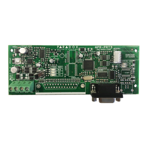
BUS2SER
RS232 Interface Module
Installation Manual
V1.20 and higher
Introduction
The BUS2SER allows you to interface the EVO bus to external systems via a
RS232 serial connection. It also provides the ability to automatically print live or
stored events.
Home Automation Interface Capabilities
When used with an EVO Series control panel, the BUS2SER can also be used
as an interface between a home automation system and your control panel. For
information on this feature and its related programming sections, refer to the
ASCII Protocol Programming Instructions and/or C-Bus Programming
Instructions available on our website at paradox.com.
Technical Specifications
Serial Port:
1 start bit, 8 data bit, no parity and 1 stop bit (8N1)
Input Voltage:
9-16 Vdc
Current Consumption:
60mA maximum
Serial Port Baud Rates: 2400, 9600, 19200 or 57600 bps
Event Buffer:
2048 events
Compatibility:
EVO192 and EVOHD control panels
Printer Requirements
Dot matrix, inkjet or laser printers can be connected through one of your
computer's COM ports to the BUS2SER module's serial port. Events can be
displayed and printed using communication software like Procomm™, Telix©
and HyperTerminal®.
It is recommended that only dot matrix printers that support a minimum of 80
columns be connected directly to the BUS2SER Module. Only dot matrix
printers can print individual events in real time.
Sample Printout:
2007/06/12
07:17
Partition 1
2007/06/12
18:09
Partition 1
LED Feedback
Panel Bus
ERROR: RX:
TX:
ON
OFF
OFF
ON
OFF
ON
ON
ON
OFF
ON
ON
ON
FLASH
OFF
OFF
Serial Bus
LED:
Condition:
RX
BUS2SER module is receiving information
TX
BUS2SER module is sending information
EVO Programming
1. Hold [0] key + [
INSTALLER CODE
2. Enter section [4003]
3. Enter module's 8-digit [
SERIAL NUMBER
4. Enter [
] and enter the required [
SECTION
BUS2SER-EI00 05/2019
Arming with master
John Doe
Disarming with master
John Doe
Condition:
Combus shorted (GND or VCC / No clock /
No data
Wrong data / Invalid combus address
(too many modules)
Reserved for future use
Combus lines are reversed (Clock in Green
/ Data in Yellow)
Low power
]
]
]
DATA
Section Description
Partition Assignment
[001]
Options [1] to [8]
Automatic Printing of Zone Status
[002]
Each section represents 8 zones i.e. [002] = zones 1~8,
to
[013] = zones 89~96. The BUS2SER module must be assigned to
[013]
the same partition as the zone.
Automatic Printing of Event Groups
] Miscellaneous Events *
[1
[2] Arming/Disarming Events
[3] Alarm and Alarm Restore Events
[4] Tamper and Tamper Restore Events
[5] Trouble and Trouble Restore Events
[6] Special Events**
[7] Access Events ***
[014]
*
Fire Reset, Contact Module Access, Remote Access, PC Fail
To Com, User Code Entered, Bypass Programmed, Delay
before Transmitting and Utility Key Pressed
** Cold Start, Warm Start, Test Reports, BabyWare Login/Logout,
Installer In/Out
*** Access Granted/Denied, Request For Exit, Door Left Open
Alarm, Door Left Open Restore, Door Forced Alarm, Door
Forced Restore
Enable Serial Port
Option [1]
The BUS2SER module can use the HyperTerminal®
communication program that comes installed with Windows®.
Using HyperTerminal®, the BUS2SER module will display events
as they occur on your computer's monitor.
1. Click Start (from the Windows® taskbar) Programs
Accessories Communications HyperTerminal®. The
Connection Description window is displayed.
2. Enter a name in the Name text box and select an icon for your
connection file. Click OK. The Connect To window is displayed.
3. From the Connect Using drop-down list select the COM port
[016]
connected to the Printer Module. Click OK. The COM
Properties window is displayed.
4. Click on the Bits per second drop-down list and select the baud
rate that is set in the BUS2SER module (Section [016] Options
[2] & [3]). By default, HyperTerminal® sets the Data bits at 8,
the Parity at None and the Stop bits at 1. Click OK.
5. The HyperTerminal® display will appear already connected to
the BUS2SER module. Click on the Properties icon (or select
Properties from the File menu). The communication file's
Properties window is displayed. Click the Settings tab. Under
Emulation, verify that it is set as Auto Detect. If not, select
Auto Detect from the drop-down list. Click OK.
Baud Settings
Option [2] [3]
Both the BUS2SER module and the
[016]
computer's serial port should have the
same baud rate. Refer to the printer's
instruction manual for the correct baud
rate.
Serial Port Usage
Option [4]
Set the BUS2SER module's serial port usage to either Event
Reporting (off) or Home Automation (on).
[016]
Note: For information on using the BUS2SER as an interface for a
home automation system, refer to the ASCII Protocol Programming
Instructions and/or C-Bus Programming Instructions available on
our website at paradox.com.
Automatic Printing of Zone Status
[020]
Each section represents 8 zones i.e. [020] = zones 97~104,
to
[025] = zones 137~144. The BUS2SER must be assigned to the
[025]
same partition as the zone.
PARADOX.COM
Advertisement

Related Manuals for Paradox BUS2SER


Summary of Contents for Paradox BUS2SER
- Page 1 [3] Alarm and Alarm Restore Events [4] Tamper and Tamper Restore Events The BUS2SER allows you to interface the EVO bus to external systems via a [5] Trouble and Trouble Restore Events RS232 serial connection. It also provides the ability to automatically print live or [6] Special Events** stored events.
- Page 2 4. 9-pin Serial Port: Connect C-Bus to the BUS2SER module using a null modem cable. 5. 9-pin Serial Port: Connect the BUS2SER module’s 9-pin serial port to a computer’s COM port to view the control panel’s events on the computer’s monitor.
Need help?
Do you have a question about the BUS2SER and is the answer not in the manual?
Questions and answers