
Related Manuals for Johnson & Starley Q-VENT CE50

Summary of Contents for Johnson & Starley Q-VENT CE50
- Page 1 Publication No. ZZ 1516-3 May 2016 Q-VENT CE50 Central Extract System INSTALLATION, COMMISSIONING & SERVICING INSTRUCTIONS www.johnsonandstarley.co.uk...
-
Page 2: Table Of Contents
CONTENTS Features Carton Content General Description Building Standards & Regulations Safety, Electrical & Water Information Technical Data Preparation & Positioning Ducting Information Positioning The Unit Spigots Handing Duct & Duct Connections Installation Instructions 10 Electrical Electrical Wiring Options Over Heat Protection 11 Specific Fan Performance 12 Sound Spectrum 13 Circuit Diagram... -
Page 3: Features
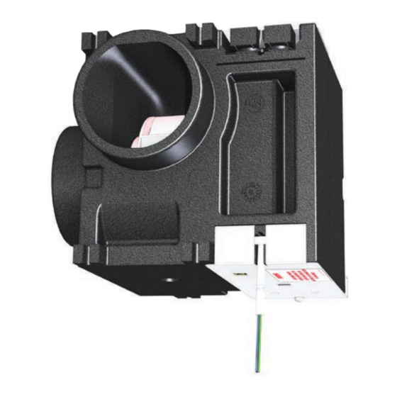
No. 8 x 50mm Wood Screws GENERAL DESCRIPTION Q-Vent CE50 Central Extract System provides mechanical exhaust ventilation from single dwellings. The unit is designed to provide low level extraction from kitchens, bathrooms, shower rooms, utility rooms and WC’s to a central extract fan via a system of ductwork and grilles. The extracted air is discharged to outside via a single duct and grille. -
Page 4: Building Standards & Regulations
7.2.3 It is the responsibility of the installer to ensure all aspects of the system design are taken into consideration. The Q-Vent CE50 is designed as a ducted unit and should only be used in ducted situations. 7.2.4 The unit has one stale air inlet spigot and one exhaust air outlet spigot. -
Page 5: Spigots
The spigot has and internal diameter of 100mm and 125mm outer diameter. HANDING 7.4.1 If Q-Vent CE50 air flow configuration is required to be handed opposite to the factory default see publication Number ZZ1518 for the correct change procedure. DUCT & DUCT CONNECTIONS For satisfactory operation of the unit, ensure ducting used is as detailed on the design drawing. -
Page 6: Electrical
Line up the unit to the surface and slide into position on the 2 fixings. The tabs will compressed slightly for a secure fit. FIGURE 5. FRONT FIXING Support the appliance and screw in the rear 2 screws with washer. DO NOT OVERTIGHTEN OR CRUSH THE FIXING TABS. -
Page 7: Specific Fan Performance
SPECIFIC FAN PERFORMANCE Performance graphs shown for two extracts, kitchen & bathroom NOTE: TABLE 2 SPECIFIC FAN POWER NAME EXTRACT RATE Kitchen +1 = 0.25 W/L/s 21 L/s Kitchen +2 = 0.28 W/L/s 29 L/s Kitchen+3 = 0.35 W/L/s 37 L/s FIGURE 7. -
Page 8: Circuit Diagram
CIRCUIT DIAGRAM COLOUR CODE BROWN BLUE BLACK GNYE GREEN/YELLOW WHITE YELLOW FIGURE 9. Q-VENT CE50 CIRCUIT DIAGRAM 12.1 ADDITIONAL CONTROLS Humidistat Sensor Pull Cord, i.e bathroom iii) Air Quality Sensor Boost Override FIGURE 10. ADDITIONAL CONTROLS COMMISSIONING 14.1 PRE COMMISSIONING CHECK Before commencing the commissioning procedure, refer to the design drawing for correct airflows. -
Page 9: Trickle Airflow Adjustment Only
14.3 TRICKLE AIRFLOW ADJUSTMENT ONLY 14.3.1 To adjust this the boost control should be OFF (NO SWITCH LIVE). NOTE: During the adjustment do not switch boost control ON (SWITCH LIVE) as this will affect the boost settings. 14.3.2 Put into installer mode. 14.3.3 To adjust the TRICKLE setting turn the RV1 clockwise ... -
Page 10: Servicing & Maintenance
The period of time the unit will run at boost speed will depend upon the type of automatic boost control fitted. 16.6 Explain the unit will need inspecting and cleaning on an annual basis. See section 15 for cleaning the fan and spigots. DIMENSIONS FIGURE 14. Q-VENT CE50 DIMENSIONS www.johnsonandstarley.co.uk... -
Page 11: Exploded Diagram
EXPLODED DIAGRAM FIGURE 165. Q-VENT CE50 EXPLODED DIAGRAM SPARE LIST ITEM PART No. DESCRIPTION 1000-0525605 PCB Assembly CE50 0520005 Fan Assembly 3 a/b 1000-0028825 Outer Fan Casing 2 part set CE50-0105005 PCB Cover Plate Sales/Replacement Telephone 01604 762881... - Page 12 Johnson & Starley Ltd Rhosili Road, Brackmills, Northampton NN4 7LZ sales@johnsonandstarley.co.uk marketing@johnsonandstarley.co.uk Reception/Customer Service 01604 762881 01604 767408 Anniversary 1922 - 2012 In the interest of continuous development Johnson & Starley reserve the right to change specifications without prior notice.
Need help?
Do you have a question about the Q-VENT CE50 and is the answer not in the manual?
Questions and answers