Digital Voice Systems AMBE-3000 HDK User Manual
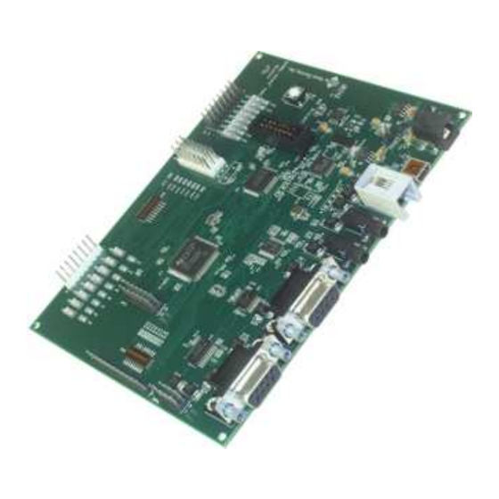
Development board
Hide thumbs
Also See for AMBE-3000 HDK:
- Specifications (2 pages) ,
- Brochure & specs (2 pages) ,
- User manual (83 pages)
Table of Contents
Advertisement
Quick Links
Download this manual
See also:
User Manual
Advertisement
Table of Contents

Related Manuals for Digital Voice Systems AMBE-3000 HDK

Summary of Contents for Digital Voice Systems AMBE-3000 HDK
- Page 1 Digital Voice Systems, Inc. The Speech Compression Specialists AMBE-3000™-HDK Development Board Version 0.4 November 17, 2008 User’s Manual...
- Page 2 Digital Voice Systems, Incorporated. Every effort has been made to ensure the accuracy of this manual. However, Digital Voice Systems, Inc. makes no warranties with respect to the documentation and disclaims any implied warranties of merchantability and fitness for a particular purpose.
- Page 3 #5,870,405, #5,649,050 and under other US and foreign patents and patents pending. AMBE, AMBE+™ and AMBE+2™ are trademarks of Digital Voice Systems, Inc. 1.6 “END USER” shall mean the person and/or organization to whom the DVSI Vocoder Product (software or hardware) was delivered or provided to as specified in the purchase order or other documentation.
- Page 4 AMBE-3000™-HDK Development Board User’s Manual Version 0.4 7.2 Except as otherwise provided in this Agreement, END USER shall not use, disclose, make, or have made any copies of the Proprietary Information, in whole or in part, without the prior written consent of DVSI. 8.
- Page 5 AMBE-3000™-HDK Development Board Information – Section User’s Manual Version 0.4 Special Handling Instructions To avoid damage from the accumulation of a static charge, industry standard electrostatic discharge precautions and procedures must be employed during handling and installation the AMBE-3000™-HDK Development Board. Read Instructions and Users Manual –...
-
Page 7: Table Of Contents
AMBE-3000™-HDK Development Board User’s Manual Version 0.4 Table of Contents Preliminary ...1 NTRODUCTION ...1 VERVIEW AMBE-3000™ HDK F AMBE-3000™ HDK D ’ NCLUDED WITH THE ONNECTORS OINTS VERVIEW OF DC P (P5) ...4 OWER USB C ONNECTION USB driver installation steps: ...5 NALOG UDIO Handset...6... - Page 8 AMBE-3000™-HDK Development Board User’s Manual Version 0.4 ACKET Decode File... 31 LoopBack Mode using the AMBE-3000™ Vocoder chip’s Parallel Interface..34 LoopBack Mode using the AMBE-3000™ Vocoder chip’s UART Interface35 KDIRECT HDK M Full Duplex Communication Setup and Control... 38 “HDK UART”...
- Page 9 AMBE-3000™-HDK Development Board User’s Manual Version 0.4 List of Figures IGURE ASIC BLOCK DIAGRAM OF THE IGURE OARD ONNECTIONS IGURE OWER NPUT 4 USB C IGURE ONNECTOR IGURE INDOWS EVICE IGURE UDIO ONNECTIONS 7 RS-232 S IGURE ERIAL IGURE EADER 9 LED ...11 IGURE...
-
Page 11: Introduction
AMBE-3000™ designs. Digital Voice Systems’ AMBE-3000™ Vocoder Chip is the core of the AMBE-3000™ HDK. All of the supporting chips on the board were chosen for their low cost, ease of use and wide availability. The control, I/O and timing of the board are handled by the Texas Instruments MSP430 microprocessor unit (MCU). -
Page 12: Included With The Hdk
Additionally, the HDK can be used to batch process files for evaluation of the vocoder. What’s Included with the HDK The development kit includes the following items: HDK evaluation board Power Adapter (120v AC to 5 V DC) Handset with cord AMBE-3000™... -
Page 13: Connectors, Test Points & Indicators
Section 2 – User’s Manual Version 0.4 Connectors, Test Points & Indicators Digital Voice Systems, Inc. The Speech Compression Specialists Overview of HDK Interfaces The AMBE-3000™ HDK is designed with flexibility in mind. It provides a variety of interfaces that allow for fast and easy integration and testing. -
Page 14: C Onnections
AMBE-3000™-HDK Development Board User’s Manual Version 0.4 Figure 2 Board Connections Board Connections0 Item Name DC Line In Handset Audio Output Audio Input Serial Port Serial Port Table 1 HDK Connectors DC Power (P5) Figure 3 Power Input Connection The AMBE-3000™-HDK Development Board operates with a 5.0 V DC power supply. Simply plug in the 120 V AC to 5.0 V DC (~250ma) power source (provided with the HKD) into an AC power source and the DC power receptacle (P5) DVSI Confidential Proprietary... -
Page 15: Usb Connection
AMBE-3000™-HDK Development Board User’s Manual Version 0.4 USB Connection The USB 2 connection on the AMBE-3000™ HDK provides system setup, mode of operation and file I/O via PC. Figure 4 USB Connector Control and operation of the HDK Board is done through the USB interface. To connect the AMBE- 3000™... -
Page 16: Analog Audio I/O
AMBE-3000™-HDK Development Board Connectors, Test Points & Indicators Section 2 – User’s Manual Version 0.4 Figure 5 Windows Device Manager Note Write down the Com Port that is being used for the TUSB3410, this value will be required to run the HDK control program. -
Page 17: 3.5Mm Phono Jacks
AMBE-3000™-HDK Development Board Connectors, Test Points & Indicators Section 2 – User’s Manual Version 0.4 voice signal. The AMBE-3000™-HDK Development Board always outputs the audio to both the 4-Wire and Handset output regardless of which voice source is selected. 3.5mm Phono Jacks The AMBE-3000™-HDK Development Board provides two 3.5 mm phono jacks (see Figure 6 Audio Connections) for the input and output of analog mono audio. -
Page 18: J Umpers
AMBE-3000™-HDK Development Board Connectors, Test Points & Indicators Section 2 – User’s Manual Version 0.4 AMBE-3000™ Vocoder Chip RS-232 (P1) The RS-232 Packet interface (P1) is connected to the UART interface of the AMBE-3000™ Vocoder chip (see AMBE-3000™ User’s Manual section 2.5.2). The UART signals of the AMBE-3000™ are put through a RS-232 receiver/driver so that the user can connect directly to a terminal or terminal emulator on a personal computer. -
Page 19: Point
AMBE-3000™-HDK Development Board User’s Manual Version 0.4 Item Header # of Pins Header 8x1 Header 8x1 ---- Header 8x1 Header 2x1 Header 4x1 Header 7x2 JP10 Header 7x2 JP11 Header 8x2 JP12 Header 8x1 JP13 Header 2x1 JP15 Header 2x1 JP16 Header 2x1 Table 2 HDK List of Headers... -
Page 20: Jp7 Handset Analog Audio I/O Test Points
AMBE-3000™-HDK Development Board User’s Manual Version 0.4 JP5 Header Pins HDK Signal Name SER_CHAN_TxD SER_CHAN_RxD SER_CHAN_CLKR SER_CHAN_CLKX SER_CHAN_FSR SER_CHAN_FSX Table 5 JP5 Serial Test Points JP7 Handset Analog Audio I/O Test Points Handset I/O Test Points Pin # Table 6 Header I/O Test Points JP8 Header JP8 Header Pins... -
Page 21: Figure 9 Led
AMBE-3000™-HDK Development Board User’s Manual Version 0.4 Table 8 Header Connections JP10 Header µController JTAG The MSP430 JTAG connector is 2x7 pins with 0.1" step that follows the TI recommended JTAG layout. PIN1 is marked with square pad on bottom. MSP430-JTAG has built-in target board voltage follower and the JTAG voltage levels follow the MSP430 target board voltage, so the target may be powered with voltage between 2.7 and 3.6 V (if the target voltage is under 2.7V Flash memory cannot be programmed). -
Page 22: Table 10 Board Status Led's
AMBE-3000™-HDK Development Board User’s Manual Version 0.4 The LCD indicators indicate the status of the HDK board as follows LED ID # Description (when LED ON) Idle Low Power / Standby Reserved Reserved Indicates Encoder/Decoder Activity Reserved Reserved Reserved µ-controller power is active 3.3 V Power on 3.3 V Power on LED Numbers... -
Page 23: Hdk Configuration
In order for a new setting to take effect, the Reset Switch must be pressed or the power to the board cycled off/on. DVSI Confidential Proprietary HDK Configuration Digital Voice Systems, Inc. The Speech Compression Specialists Page 13... -
Page 24: Slide Dip-Switch Settings
AMBE-3000™-HDK Development Board User’s Manual Version 0.4 Figure 11 Vocoder Settings Switches SW1 and SW2 Note: As viewed in Figure 11 Switch 1 is set to “ON” when the white switch is positioned to the left and Switch 2 is set to “ON” when the white switch is in the up position. Slide Dip-Switch Settings Board Switches Item... -
Page 25: Rate
AMBE-3000™-HDK Development Board User’s Manual Version 0.4 user is able to choose a rate through the PC interface when the HDK is attached to a PC via USB. The user can recompile the AMBE-3000™ HDK source code to achieve any rate that they require. After the HDK is reset, it resets the AMBE-3000™... -
Page 26: Jp11 Header Led Indicators
AMBE-3000™-HDK Development Board User’s Manual Version 0.4 JP4 Header Table 14 JP2 to JP4 Header Jumpers JP11 Header LED Indicators The JP11 header enables LEDs D19 through D26 to be active. These LEDs are used to indicate the current status on the HDK Mode. All Jumpers should be installed on this header. JP11 Header Pins 1 - 2... -
Page 27: Jp11 Header Usb Power
AMBE-3000™-HDK Development Board User’s Manual Version 0.4 JP11 Header USB Power The HDK can be powered from the Power connector P5 only. JP16 Header Pins Use 5 Volts Power source from 1 - 2 Power Connector P5 Table 18 JP16 USB 5 Volt Power DVSI Confidential Proprietary Jumper Installed... -
Page 28: Operation
RS-232 port interface (P1) Note: a Serial to USB adapter is required. -mode a3kdirect Sets the HDK mode to a3kdirect Dual HDK Mode --- directly connects two AMBE-3000 HDK’s together using the RS-232 channel interface (P2). -mode dualhdkskew -mode dualhdk Table 19 HDK Modes *Note: To run in Codec Play/Record or Packet Modes start in Idle Mode. -
Page 29: Hdk To Ambe-3000™ Vocoder Chip Interface
AMBE-3000™-HDK Development Board User’s Manual Version 0.4 HDK to AMBE-3000™ Vocoder Chip Interface The USB interface on the HDK is used for board setup and control. The HDK provides access to the parallel and UART interfaces on the AMBE-3000™ vocoder chip. When running in Codec Play /Record Mode, Packet Mode or Loopback Mode the user can select either PPT or UART interface to use. -
Page 30: Hdk Software
AMBE-3000™-HDK Development Board User’s Manual Version 0.4 HDK Software The AMBE-3000™ HDK Vocoder board is set-up, controlled and operated from a PC. In order for the PC to work with the HDK a USB cable must be used and USB drivers must be installed. See the USB Connection Section on how to install the USB drivers. -
Page 31: Running The Hdk Control Software
AMBE-3000™-HDK Development Board User’s Manual Version 0.4 <file name>-r<rate index #>.bita -- (encoded data from an a-law file) compressed speech files from a .pcma (a-law) format file, that are encoded (recorded) at a data rate as indicated by the rate index number that follows the -r. For example, dvsi-r39.bit is a compressed data file encoded at rate index 39 which is a data rate of 3600bps. - Page 32 AMBE-3000™-HDK Development Board User’s Manual Version 0.4 PC communications port settings format -port COM<#> <baud rate> [Interface Selection] The interface selection option specifies which AMBE-3000™ Vocoder chip interface (UART or Parallel) is used to connect to the MSP µcontroller. See Table 20 HDK AMBE-3000™ Interfaces Interface Selection format -uart -ppt...
- Page 33 AMBE-3000™-HDK Development Board User’s Manual Version 0.4 [Vocoder Options] The HDK provides the ability to set the data rate and noise suppression of the AMBE-3000™ Vocoder chip. Vocoder Options Format -r <”rate index#” or “custom rate words”> where the ”rate index#” sets the bit rate of the AMBE-3000™ encoder/decoder See Table 21 Standard Rate Table for AMBE-3000.
-
Page 34: Idle Mode
AMBE-3000™-HDK Development Board User’s Manual Version 0.4 -record <time (in seconds)> with this selection the PC controls the HDK to set the AMBE-3000™ vocoder chip into codec mode and speech data from the audio input gets encoded. For each channel packet that is output by the HDK the PC extracts the channel data and writes it to the file <outfile>. -
Page 35: Play File To Audio Output
AMBE-3000™-HDK Development Board Operation User’s Manual Version 0.4 Note: The hdkcom.exe program automatically switches the HDK into Codec Play/Record Mode (–mode codec) when the command line uses any one of these three options. After the file is played/recorded the HDK is automatically switched back into idle mode. If it is desired to keep the HDK in Codec Play/Record mode to be ready to process audio then the –mode codec option must be used in the command line. -
Page 36: Record Input Audio To File
AMBE-3000™-HDK Development Board User’s Manual Version 0.4 Codec Play Audio Output Command Example of playing an encoded (3600bps) file out the audio output hdkcom.exe –port COM4 460800 where -port COM4 is the PC’s COM port that the HDK communicates on as indicated by Windows Device Manger 460800 is the baud rate of the PC connection sets the HDK to use the PPT Interface of the AMBE-3000™... - Page 37 AMBE-3000™-HDK Development Board User’s Manual Version 0.4 Codec RECORD Audio Input Command Example: hdkcom.exe –port COM4 460800 where -port COM4 is the PC’s COM port that the HDK communicates on as indicated by Windows Device Manger 460800 is the baud rate of the PC connection sets the HDK to use the PPT Interface of the AMBE-3000™...
-
Page 38: Play/Record Audio
AMBE-3000™-HDK Development Board User’s Manual Version 0.4 Play/Record Audio -playrecord is used to perform both record of the audio input and play a file out the audio output at the same time. Figure 14 Play / Record -playrecord Block Diagram Codec PLAY/RECORD Audio Command Example: hdkcom.exe –port COM4 460800 dvsi36.bit rec1.bit... -
Page 39: Packet Mode
AMBE-3000™-HDK Development Board User’s Manual Version 0.4 -port COM4 is the PC’s COM port that the HDK communicates on as indicated by Windows Device Manger 460800 is the baud rate of the PC connection sets the HDK to use the PPT Interface of the AMBE-3000™ Vocoder chip -ppt sets the HDK to use the UART Interface of the AMBE-3000™... -
Page 40: Block
AMBE-3000™-HDK Development Board User’s Manual Version 0.4 Figure 15 Packet Mode –enc PPT Interface Block Diagram Figure 16 Packet Mode -enc UART Interface Block Diagram Packet Mode Encode File Example hdkcom.exe –port COM4 460800 dvsi36tst.bit where COM4 is the COM port on the PC that the HDK will communicate on DVSI Confidential Proprietary Command Prompt –uart or –ppt... -
Page 41: Decode File
AMBE-3000™-HDK Development Board User’s Manual Version 0.4 460800 is the baud rate of the PC connection sets the HDK to use the PPT Interface of the AMBE-3000™ Vocoder chip -ppt sets the HDK to use the UART Interface of the AMBE-3000™ Vocoder chip -uart If neither –ppt or –uart is specified the PPT interface is used by default. -
Page 42: Block
AMBE-3000™-HDK Development Board User’s Manual Version 0.4 Figure 17 Packet Mode -dec PPT Interface Block Diagram Figure 18 Packet Mode -dec UART Interface Block Diagram Packet Mode Decode File Example: hdkcom.exe –port COM4 460800 dvsi36tst.pcm where COM4 is the COM port on the PC that the HDK will communicate on 460800 is the baud rate of the PC connection sets the HDK to use the PPT Interface of the AMBE-3000™... -
Page 43: Figure 19 Packetm
AMBE-3000™-HDK Development Board User’s Manual Version 0.4 To validate that the file was decoded correctly simply compare the created file dvsi36tst.pcm with the similar file dvsi36.pcm included on the HDK CD. In the HDK directory use the following DOS command. cmp dvsi36.pcm dvsi36tst.pcm no differences encountered Figure 19 Packet Mode Encode/Decode PPT Interface Block Diagram... -
Page 44: Loopback Mode
AMBE-3000™-HDK Development Board User’s Manual Version 0.4 Figure 20 Packet Mode UART Interface Block Diagram Packet Mode Encode/Decode File Command Example: Command Prompt hdkcom.exe –port COM4 460800 index or rate words in hex> -encdec <input filename> <output filename> where COM4 is the COM port on the PC that the HDK will communicate on 460800 is the baud rate of the PC connection -r is the rate index of the bit rate the file is to be decoded at. -
Page 45: Loopback Mode Using The Ambe-3000™ Vocoder Chip's Uart Interface35
AMBE-3000™-HDK Development Board Operation User’s Manual Version 0.4 Figure 21 LoopBack PPT Mode AMBE-3000™ Vocoder Chip (Parallel Interface) LoopBack Mode using the AMBE-3000™ Vocoder chip’s UART Interface In Loopback the AMBE-3000™ Vocoder chip UART Interface Analog speech input from the handset or RCA jack input connections gets digitized by the codec then encoded the AMBE-3000™... -
Page 46: A3Kdirect Mode
A3kdirect Mode A3kdirect Mode is used so that the AMBE-3000 HDK can connect the AMBE-3000™ Vocoder Chip’s UART Interface to a PC across the RS-232 channel interface (P1). This physical link establishes a communication connection where the PC can send any packets (speech, channel or control) directly to the vocoder chip’s UART Interface and get either Compressed speech or PCM packets in return. -
Page 47: Dual Hdk Mode (Full Duplex)
Dual HDK Mode (Full Duplex) The AMBE-3000 HDK can be directly connected to a second AMBE-3000 HDK using the RS-232 channel interface (P2). This physical link establishes a real-time, full-duplex communication connection between the two units. Each board can select either the handset or line-in input as the audio source. -
Page 48: Full Duplex Communication Setup And Control
AMBE-3000™-HDK Development Board User’s Manual Version 0.4 decoded by first AMBE-3000™-HDK Development Board. The HDK Board implements an asynchronous RS-232 serial interface for channel data using a protocol designed by DVSI. Figure 23 Full Duplex Mode Full Duplex Communication Setup and Control To set up a full duplex communication system between two HDK boards, each board must be individually configured and then the connection (P2 to P2) between the two boards can be made. - Page 49 AMBE-3000™-HDK Development Board User’s Manual Version 0.4 -mode dualhdkskew is to set the board into Dual HDK Mode with skew ON Note: Once the HDK is set to Dual HDK Mode it will stay in this mode until another command is issued to put it into another mode.
-
Page 50: Figure 24 Two Hdk
AMBE-3000™-HDK Development Board Operation User’s Manual Version 0.4 ☺ ☺ ☺ ☺ ☺ ☺ ☺ ☺ ☺ Figure 24 Two HDK boards connected together Figure 25 RS-232 Null Modem Cable Pin-out This cable configuration is used for “Dual-HDK Mode”, Codec Mode UART Interface, Packet Mode UART Interface and “UART Loopback Mode”. -
Page 51: Hdk Uart" Data Packet Structure
AMBE-3000™-HDK Development Board Operation User’s Manual Version 0.4 Figure 26 RS-232 Straight through Cable Pin-out This cable is used for connecting the RS-232 interface to a PC or other serial device. “HDK UART” Data Packet Structure Data packets sent as byte-aligned frames over the asynchronous RS-232 UART Serial interface. This helps maintains compatibility with asynchronous 8N1 framing and synchronization if channel errors exist. -
Page 52: Documentation & Software Development
The TUSB3410 USB drivers are required and may be downloaded at ti.com. Third Party Tools MSP-430 Flash Programmer Part Number: MSP-PRGS430 http://focus.ti.com/docs/toolsw/folders/print/msp-prgs430.html MSPGCC MSP-430 GNU Compiler http://mspgcc.sourceforge.net/ DVSI Confidential Proprietary Documentation & Software Development Documentation & Section 4 – Digital Voice Systems, Inc. The Speech Compression Specialists Page 42... -
Page 53: Specifications
Connected to Pins 4 and 6 Tx Channel Out Rx Channel In Connected to Pins 1 and 6 Connected to Ground Connected to Pins 1 and 4 Tx Channel Out Rx Channel In No Connection Digital Voice Systems, Inc. The Speech Compression Specialists Page 43... -
Page 54: User's Manual Version
AMBE-3000™-HDK Development Board User’s Manual Version 0.4 USB Serial Port (P6) Type Connector USB Pin Out Pin Number 6, 7, 8, 9 Audio I/O Connections Line In (J2) Type Connector Maximum Input Level: Input Impedance Bandwidth D/A Resolution D/A Sampling Rate: SNR (Non-Weighted) Note: A 1.414 V signal on the line input produces digital max when the codec input gain is 0 dB. -
Page 55: Header Connections
AMBE-3000™-HDK Development Board User’s Manual Version 0.4 Handset Pin Out (RJ11 Connector) Pin # Signal Name Connected to Ground Analog Out P1 Speaker Out Microphone In/DC Microphone Bias out Handset Header (JP7) Pin Number Header Connections DSP JTAG (J15) Pin Number Name TRSTn Digital Ground... -
Page 56: Appendix
0x0000 0x0000 0x0765 0x2010 0x0000 0x0763 0x0001 0x0000 0x0763 0x0005 0x180C Appendix Section 6 – Digital Voice Systems, Inc. The Speech Compression Specialists Switch 1 Settings Positions 1-6 RCW 4 RCW 5 0x0000 0x6428 0x0000 0x722D 0x0000 0x4330 0x0000 0x6930... -
Page 57: Hdk Ambe-3000™ Interfaces Table 21 Standard Rate Table For Ambe-3000
AMBE-3000™-HDK Development Board User’s Manual Version 0.4 4800 0x0460 4550 0x045B 2450 2350 0x0431 3600 1200 0x0448 4000 0x0450 6000 2450 3550 0x0431 4150 2250 0x0053 6400 0x0280 4000 2400 0x0250 6400 3600 2800 0x0248 6400 0x0480 4000 2400 0x0450 4400 2800 0x0058... - Page 58 AMBE-3000™-HDK Development Board User’s Manual Version 0.4 Rate Index Rate Index DVSI Confidential Proprietary 4800 4800 9600 9600 2400 2350 9600 4850 4800 4550 4800 3100 7200 4400 6400 4150 3600 3350 8000 7750 8000 4650 4000 3750 4000 4000 AMBE-2000™...
- Page 59 AMBE-3000™-HDK Development Board User’s Manual Version 0.4 DVSI Confidential Proprietary 4800 2450 6000 2450 7200 2450 4000 2600 4800 3600 4800 4000 6400 4000 7200 4400 8000 4000 9600 3600 Appendix Section 6 – 2350 3550 4750 1400 1200 2400 2800 4000 6000...
-
Page 60: Msp430 Input/Output Pin Description
AMBE-3000™-HDK Development Board User’s Manual Version 0.4 MSP430 Input/Output Pin Description MSP430 Input/Output Pin Description Description CODEC_FS_MSPn TXRDY RXRDY PPTACK TXFRM SER_RTS SER_CTS USB_SER_CTSn USB_SER_RTSn JP12 pin 8 JP12 pin 7 JP12 pin 6 JP12 pin 5 JP12 pin 4 JP12 pin 3 JP12 pin 2 JP12 pin 1... -
Page 61: Additional Reference Material
AMBE-3000™-HDK Development Board User’s Manual Version 0.4 Additional Reference Material AMBE-3000™ vocoder chip Users Manual http://www.dvsinc.com/literature.htm Application Report – Understanding Data Converters: http://www-s.ti.com/sc/psheets/slaa013/slaa013.pdf DVSI Confidential Proprietary Appendix Section 6 – Page 51... -
Page 62: Support
AMBE-3000™-HDK Development Board Support Section 7 – User’s Manual Version 0.4 Support Digital Voice Systems, Inc. The Speech Compression Specialists DVSI Contact Information If you have problems or questions about the AMBE-3000™-HDK Development Board please contact: Digital Voice Systems, Inc. -
Page 63: Table Of Revisions
AMBE-3000™-HDK Development Board User’s Manual Version 0.4 Table of Revisions History of Revisions Revision Date of Description Number Revision Oct. 22, 2008 Added descrition to SW2 Pin 1 Corrected Switch Positions in Table 21 Standard Rate Table for AMBE-3000™ Nov. 17, 2008 Added Steps 3 and 4 to HDK Software installation description NOTES... - Page 64 AMBE-3000™-HDK Development Board Support Section 7 – User’s Manual Version 0.4 Page 54 DVSI Confidential Proprietary...
Need help?
Do you have a question about the AMBE-3000 HDK and is the answer not in the manual?
Questions and answers