Sign In
Upload
Manuals
Brands
Digital Voice Systems Manuals
Recording Equipment
AMBE-3000 HDK
Digital Voice Systems AMBE-3000 HDK Manuals
Manuals and User Guides for Digital Voice Systems AMBE-3000 HDK. We have
4
Digital Voice Systems AMBE-3000 HDK manuals available for free PDF download: User Manual, Specifications, Brochure & Specs
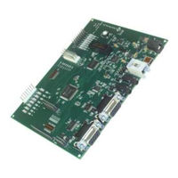
Digital Voice Systems AMBE-3000 HDK User Manual (64 pages)
Development Board
Brand:
Digital Voice Systems
| Category:
Computer Hardware
| Size: 4 MB
Table of Contents
Table of Contents
7
Introduction
11
Overview
11
Ambe-3000™ Hdk Features
11
Ambe-3000™ Hdk Description
11
Included with the Hdk
12
Connectors, Test Points & Indicators
13
Overview of Hdk Interfaces
13
C Onnections
14
DC Power (P5)
14
Able 1 Hdk Connectors
14
Figure 2 Boardc
14
Figure 3 Power Input
14
Usb Connection
15
USB Driver Installation Steps
15
Onnector
15
Analog Audio I/O
16
Handset
16
Figure 5 Windowsd
16
Figure 6 Audioc
16
3.5Mm Phono Jacks
17
Rs-232 Connections
17
Controller RS-232 Connection (P2)
17
J Umpers
18
AMBE-3000™ Vocoder Chip RS-232 (P1)
18
Hdk List of Headers
18
Figure 8 Header Test
18
Point
19
Hdk Test Points
19
JP1 LED Indicators Test Points
19
JP5 Header Serial Interface Test Points
19
Able 2 Hdk List of Eaders
19
Table 3 Header Test Points
19
Able 4 Jp1 Test Oints
19
JP7 Handset Analog Audio I/O Test Points
20
JP8 Header
20
Header Connections
20
Able Jp5 Jpjp5 Serial Test Points
20
Table 6 Header I/O Test Points
20
Able 7 Jp8 Serial Ata
20
Figure 9 LED
21
JP10 Header Μcontroller JTAG
21
HDK Board Status Indicator Leds
21
Table 8 Header Connections
21
Table 9 Jp10 Msp430 Jtag
21
Table 10 Board Status Led's
22
Hdk Configuration
23
Overview
23
Board Reset
23
AMBE-3000™ Vocoder Chip Configuration Via Dip-Switches
23
Figure 10 Resets
23
Slide Dip-Switch Settings
24
Vocoder Rate Selection
24
Table 11 Board Dip Switches
24
Figure 11 Vocoder
24
Rate
25
Ambe-3000™ Uart Interface Baud Rate Selection
25
Hdk Configuration Jumpers
25
JP2, JP4 and JP12 Headers Jumpers
25
Able 12 Ambe-3000™ Uart Baud Rate Selection
25
Table 13 Jumper Header Connectors
25
JP11 Header LED Indicators
26
JP13 Header Codec_Input Select
26
JP15 Header WD Disable
26
Able 16 Jp13 Codec Input Selection
26
Table 14 Jp2 to Jp4 Header Jumpers
26
Able 15 Jp11 Enable Led Indicators
26
Able 17 Jp15 Wd Disable
26
JP11 Header USB Power
27
Table 18 Jp16 Usb 5 Volt Power
27
Operation
28
Operating Modes
28
Table 19 Hdk Modes
28
Hdk to Ambe-3000™ Vocoder Chip Interface
29
Data Pass through
29
Able 20 Hdk Ambe-3000™ Interfaces
29
Hdk Software
30
Installing HDK Program File on Windows Vista/Xp
30
Running the Hdk Control Software
31
Idle Mode
34
Codec Play/Record Mode
34
Play File to Audio Output
35
Figure 12 Play / R
35
Record Input Audio to File
36
Figure 13 Play / R
36
Play/Record Audio
38
Figure 14 Play / R
38
Packet Mode
39
Block
40
Figure 15 Packetm
40
Figure 16 Packetm
40
Decode File
41
Block
42
Figure 17 Packetm
42
Figure 18 Packetm
42
Figure 19 Packetm
43
Loopback Mode
44
Loopback Mode Using the AMBE-3000™ Vocoder Chip's Parallel Interface
44
Figure 20 Packetm
44
Loopback Mode Using the AMBE-3000™ Vocoder Chip's UART Interface35
45
Figure 21 Loop Back
45
Figure 22 Loop Back
45
A3Kdirect Mode
46
Dual HDK Mode (Full Duplex)
47
Full Duplex Communication Setup and Control
48
Figure 23 Full Duplex
48
Figure 24 Two Hdk
50
Hdk Uart" Data Packet Structure
51
Documentation & Software Development
52
Documentation
52
Software
52
Third Party Tools
52
Specifications
53
Overview
53
Board Connections
53
User's Manual Version
53
User's Manual Version
54
Audio I/O Connections
54
Header Connections
55
Electrical Input
55
Mechanical
55
Appendix
56
Rate Tables
56
Hdk Ambe-3000™ Interfaces Table 21 Standard Rate Table for Ambe-3000
57
MSP430 Input/Output Pin Description
60
Software Development
60
Additional Reference Material
61
Support
62
Dvsi Contact Information
62
Table of Revisions
63
Advertisement
Digital Voice Systems AMBE-3000 HDK User Manual (83 pages)
Vocoder Chip
Brand:
Digital Voice Systems
| Category:
Recording Equipment
| Size: 2 MB
Table of Contents
Speech Packet Example
2
Channel Packet Example
2
Table of Contents
5
List of Figures
7
List of Tables
7
Version 1.05, February 19, 2008
8
Product Introduction
10
Advances in Vocoder Design
10
AMBE-3000™ Vocoder Chip Features
10
Typical Applications
11
Initial Design Considerations
12
Vocoder Speech and FEC Rate Selection
12
Operating Modes
12
Codec Mode
13
Packet Mode
13
Switching between Codec Mode and Packet Mode Using Packets
14
Interface Selection
14
A/D - D/A Codec Chip Selection
15
Special Functions Description
15
Voice Activity Detection (VAD), Comfort Noise Insertion (CNI) (DTX_ENABLE Pin 5)
15
Echo Canceller (EC_ENABLE Pin 120)
15
DTMF Dual Tone Multiple Frequency, Detection and Generation
16
Soft Decision Error Correction
16
Skew Control (SK_ENABLE Pin 6)
17
Noise Suppressor (NS_ENABLE Pin 7)
17
Companding Using A-Law and Μ-Law
17
I/O Management
18
I/O Handler in Codec Mode
20
I/O Handler in Packet Mode
21
Hardware Information
23
Special Handling Instructions
23
Package Detail
24
Package Type
25
AMBE-3000™ Chip Markings
26
Pin out Table
27
Hardware Configuration Pins
31
SPI Interface
32
UART Interface
33
Mcbsp Interface
33
Mcbsp Selected for Codec Interface
34
Mcbsp Selected for Packet Interface
35
Parallel Interface
36
Parallel Port Packet Interface
36
Low Power Modes
38
Run State
39
Idle State
39
(Subject to Change) DVSI CONFIDENTIAL PROPRIETARY
39
Standby State
39
Halt State
39
Power Modes
39
Low Power Mode When Using the UART Packet Interface
40
Low Power Mode When Using the Mcbsp Packet Interface
40
Low Power Mode When Using the Mcbsp Codec Interface
40
Low Power Mode When Using the SPI Codec Interface
40
Low Power Mode When Using the Parallel Packet Interface
40
Additional Requirements When Low Power Mode Is Enabled
40
Typical AMBE-3000™ Vocoder Chip Power Measurements
41
Electrical Characteristics and Requirements
42
Normal Operating Conditions
42
Recommended Operating Conditions
42
Absolute Maximum Ratings
43
Thermal Resistance Characteristics
43
Power Sequencing Requirements
43
Power-Down Sequencing
43
Signal Transition Levels
44
Vocoder Front End Requirements
45
Interfacing a Codec to the AMBE-3000™ Vocoder Chip
47
The Texas Instruments General Purpose TLV320AIC14
47
The Texas Instruments PCM3500 General Purpose Codec
48
Overview
49
Codec Mode Operation
49
Packet Mode Operation
49
Packet Interfaces
50
Packet Format
50
START_BYTE (1 Byte)
50
LENGTH (2 Bytes)
50
TYPE (1 Byte)
50
Packet Fields
51
Parity Field
51
Control Packet Format (Packet Type 0X00)
52
Control Packet Fields and Response Fields
52
Input Speech Packet Format (Packet Type 0X02)
66
Speech Packet Fields
66
Output Speech Packets Format (Packet Type 0X02)
68
Input Channel Packet Format (Packet Type 0X01)
68
Channel Packet Fields
68
(Subject to Change) DVSI CONFIDENTIAL PROPRIETARY
70
Example Packets
70
Speech Packet Example
70
Speech Packet Example 2
71
Channel Packet Example
72
Channel Packet Example 2
73
Output Channel Packet Format (Packet Type 0X01)
70
Total Algorithmic Delay
74
Vocoder Rate by Index Number
74
Rate - Control Words / Configuration Pin Settings
75
DVSI Contact Information
78
Environmental Specifications
79
History of Revisions
83
Digital Voice Systems AMBE-3000 HDK Specifications (2 pages)
Vocoder Chips
Brand:
Digital Voice Systems
| Category:
Recording Equipment
| Size: 0 MB
Advertisement
Digital Voice Systems AMBE-3000 HDK Brochure & Specs (2 pages)
Hardware Development Kit
Brand:
Digital Voice Systems
| Category:
Computer Hardware
| Size: 3 MB
Advertisement
Related Products
Digital Voice Systems AMBE-2000
Digital Voice Systems AMBE-2020
Digital Voice Systems AMBE-20X0 HDK
Digital Voice Systems AMBE-20x0-HDK
Digital Voice Systems VC-20
Digital Voice Systems Categories
Recording Equipment
Computer Hardware
Network Hardware
More Digital Voice Systems Manuals
Login
Sign In
OR
Sign in with Facebook
Sign in with Google
Upload manual
Upload from disk
Upload from URL