Table of Contents
Advertisement
Advertisement
Table of Contents

Related Manuals for Buehler IsoMet 4000


Summary of Contents for Buehler IsoMet 4000
- Page 1 IsoMet™ 4000 Linear Precision Saw MA112680_39.3 4/2014...
- Page 2 Continually improve our performance in all aspects of the business. About Buehler For over 70 years, Buehler has been a leading manufacturer of scientific instruments and supplies for use in materials analysis. Buehler products are used throughout the world in manufacturing facilities, quality laboratories and universities to analyze all types materials, including: •...
- Page 3 The information contained in this communication is intended only for the use of the individual or entity to which it is addressed and may contain information that is privileged, confidential and exempt from disclosure under applicable law. © 2010 – 2012 Buehler, a division of Illinois Tool Works Inc. All rights reserved. MA112680_39.3...
- Page 4 This page was intentionally left blank. MA112680_39.3 [Original Instructions] 4/2014...
-
Page 5: Table Of Contents
Vises ................................6 External Recirculating System ........................7 IsoMet 4000 Controls and Functions ......................8 Front Panel Controls ..........................8 IsoMet 4000 Display Screens and Commands ................... 10 Parameter Fields ..........................10 L1 Display Screen..........................11 L1 Display Screen Commands ...................... 11 Pause CUTTING CYCLE ....................... - Page 6 Cleaning the Unit ..........................26 Automatic Blade Dressing ........................26 Cleaning the Automatic Blade Dressing shaft ................26 Checking the Blade Motor Total Hours ....................27 Troubleshooting Chart ..........................28 Application Guide ............................29 Buehler Environmental Policy ........................31 MA112680_39.3 [Original Instructions] 4/2014...
-
Page 7: Isomet 4000 Linear Precision Saw
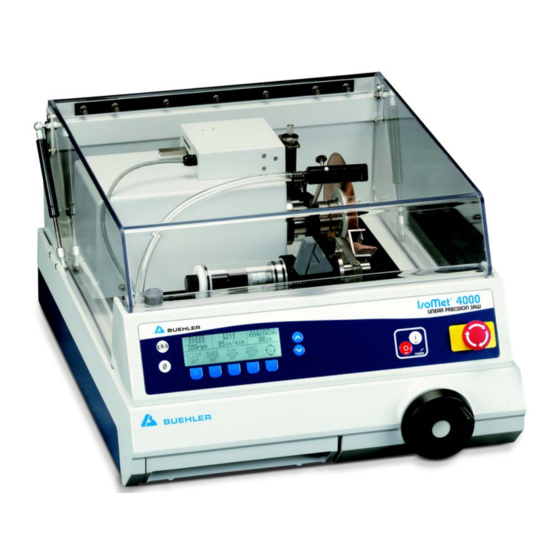
IsoMet 4000 Linear Precision Saw The IsoMet 4000 is an easy to use automatic linear saw that includes the SMARTCUT system to automatically adjust the feed rate to provide consistent, quality cuts and to prevent specimen and machine damage. A 1µm Specimen Positioning System allows for precise applications and enables the cutting of delicate specimens with minimal deformation. -
Page 8: Safety Information
(41° F to 104° F / 5° C to 40° C) and non-condensing humidity ranges (30-90%). Machine Use and Care All operators should be trained in the use of the IsoMet 4000. If training is needed contact Buehler at 800.BUEHLER (800.283.4537) or your local Buehler Sales Representative. -
Page 9: Safety Terms
NOTICE indicates practices not related to personal injury. Unpacking The IsoMet 4000 Linear Precision Saw is shipped fully assembled and has been carefully packaged to protect it during transit from the factory to your location. Carefully unpack and check contents. -
Page 10: Installation
Lift the IsoMet 4000 Linear Precision Saw out of the carton and position it on a table so it overhangs the edge. Remove all bolts securing the IsoMet 4000 Linear Precision Saw to the wood base. -
Page 11: Blade Installation
Blade Installation Flanges support the wafering and abrasive blades. Failure to provide adequate flange support may result in curved cuts and damaged blades. When cutting always select the maximum flange diameter in proportion with the size of the specimen. Installing a Blade 1. -
Page 12: Cooling And Lubrication
• During high frequencies of use or when using abrasive cut-off wheels with the IsoMet 4000 Linear Precision Saw, the coolant tank should be cleaned regularly. The drain screen should be cleaned between each cut to prevent blockage. -
Page 13: External Recirculating System
External Recirculating System WARNING Personal Injury. Disconnect the power supply before performing any maintenance or adjustments. 1. Determine a location for the External Recirculating System. 2. Set the tank on a four-wheeled recirculating cart (P/N 16-1497). 3. Slide the 1-inch drain hose over the drain outlet pipe and secure the drain hose with the supplied hose clamp (see Figure 2) 4. -
Page 14: Isomet 4000 Controls And Functions
When raised, the counter-balanced hood will remain in the open position, activating a safety-lock switch disabling the controls for the cutting motor. 1. Activate power to the IsoMet 4000. Flip the power switch on the back of the machine to the ON position. - Page 15 Once a position is determined, press the ZERO button and the DISTANCE REMAINING value will change to .00, indicating the SOFT HOME position. Increase The Increase button will incrementally increase (raise) a parameter’s value. The maximum values for the IsoMet 4000 are: • BLADE SPEED = 5000 rpm •...
-
Page 16: Isomet 4000 Display Screens And Commands
IsoMet 4000 Display Screens and Commands Parameter Fields There are four (4) different parameter fields available. Use the SCROLL button to scroll though the LCD Screens to display and highlight the parameters. BLADE FEED DISTANCE Parameter fields are highlighted using the... -
Page 17: L1 Display Screen
L1 Display Screen BLADE FEED DISTANCE SPEED RATE REMAINING 4250rpm .64in/min 1.00in CUTTING BLADE PUMP FEED CYCLE MOTOR MOTOR MOTOR L1 Display Screen Commands Button [1] CUTTING CYCLE starts, stops, and pauses the cutting cycle. Button [2] BLADE MOTOR activates [ON] or deactivates [OFF] the blade motor. The blade will rotate at a set speed and the hood must be closed. -
Page 18: L2 Display Screen
L2 Display Screen BLADE FEED DISTANCE SPEED RATE REMAINING 4250rpm .64in/min 1.00in CUTTING ROTATING SOFT SOFT CYCLE CHUCK START START L2 Display Screen Commands Button [1] CUTTING CYCLE starts, stops, and pauses the cutting cycle. Button [2] ROTATING CHUCK activates [ON] or deactivates [OFF]. The chuck will rotate at a constant speed. -
Page 19: L3 Display Screen
L3 Display Screen BLADE FEED DISTANCE SPEED RATE REMAINING 4250rpm .64in/min 1.00in CUTTING DRESS SELECT IMPERIAL CYCLE BLADE ENGLISH UNITS LANGUAGE L3 Display Screen Commands Button [1] CUTTING CYCLE starts, stops, and pauses the cutting cycle. Button [2] DRESS BLADE sets the correct blade-dressing parameters and activates the automatic dressing mechanism (if attached). -
Page 20: Specimen Positioning
Specimen Positioning Specimen Loading Several chucks are available to hold specimen of many different sizes and shapes. Select the proper chuck for the particular application and attach it to the T-slot bed. CAUTION Equipment Damage. Secure the specimen into the chuck and the chuck to the vise bed to prevent slipping or rotation during cutting. - Page 21 3. Program this value into the CUTTING LENGTH field. The DISTANCE REMAINING parameter field will change to the CUTTING LENGTH parameter field when highlighted with the SCROLL button. BLADE FEED CUTTING SPEED RATE LENGTH 600 rpm .75 in/min .60 in a.
-
Page 22: Positioning A Specimen With A Known Thickness
Positioning a Specimen with a Known Thickness 1. Position the specimen in the chuck. 2. Turn the hand crank clockwise until the blade is beyond the chuck position (see Figure 9). 3. Turn the hand crank counter-clockwise to bring the blade forward until it is just behind and almost touching the specimen (see Figure 10). -
Page 23: Operation
ON position. The CUTTING CYCLE command is accessible in the L1, L2, and L3 display screens. DANGER Personal Injury. The IsoMet 4000 Linear Precision Saw is designed to only operate with the cover closed. Efforts to defeat the safety interlock could result in personal injury and void warranty. -
Page 24: Manual Cutting
NOTICE Too large of a specimen may cause the flange to advance into the specimen causing damage to both the flange and specimen. If you need to cut large specimen, reposition the specimen using a different mount or use a larger blade. During operation observe the saw’s performance. -
Page 25: Smart Cut: Checking And Adjusting The Feed Rate
SMART CUT: Checking and Adjusting the Feed Rate During the CUTTING CYCLE, the IsoMet 4000 will monitor the load that is applied to the blade. If an overload condition occurs, the IsoMet 4000 will automatically decrease the FEED RATE to maintain an optimum cutting condition. -
Page 26: Dressing The Blade
If a 3-inch blade is used, slide the T-mount so the left-end of the dressing stick does not hit the spindle base. If the Automatic Dressing System is not attached, insert a dressing stick in a specimen holder. Place the specimen holder in the path of the blade and clamp it securely. -
Page 27: Automatic Blade Dressing, Rotating Chuck, And Specimen Positioning System
Automatic Blade Dressing, Rotating Chuck, and Specimen Positioning System The IsoMet 4000 is shipped with the Specimen Positioning System and Automatic Dressing System already attached. The following instructions are for replacing the Automatic Dressing System, the Specimen Positioning System, and a Rotating Chuck. -
Page 28: Installing The Specimen Position System
1. Clean the mounting embossment if the X T-slot bed is not installed. 2. Attach the T-slot table to the IsoMet 4000 (there will be four (4) screws). 3. Align the T-nut and posts on the bottom of the Specimen Positioning System to the T-slot and slide into position. -
Page 29: Installing The Automatic Blade Dressing System
Installing the Automatic Blade Dressing System 1. Clean the top of the turret of all cutting materials and fluids. 2. Place the Automatic Blade Dressing unit with the mounting flange down and to the right. 3. Align the mounting holes. 4. -
Page 30: Warning Messages
The hood is not fully closed. Check to see if any specimens or other debris is on the hood ledge. ARM LIMIT The IsoMet 4000 has a safety switch to limit the blade’s forward travel. Use the hand crank to reposition the blade. BLADE PINCHED Indicates that during cutting the blade became pinched by the specimen and the cutting operation has automatically shut off. -
Page 31: Maintenance
Maintenance The IsoMet 4000 Linear Precision Saw will continue to perform at optimum levels with proper care, daily cleaning, and general maintenance. The protective hood and touch-panel control pad should be cleaned using mild soap and water applied ® with a soft cloth. Do not use ammonia-based cleaners, i.e. Windex . -
Page 32: Cleaning The Unit
Cleaning the Unit The IsoMet 4000 Linear Precision Saw should be cleaned periodically to prevent build-up of cutting residue and cutting fluids and the coolant line can be used to rinse the saw. The linear rails should be cleaned daily and with heavy use should be lubricated with light oil. -
Page 33: Checking The Blade Motor Total Hours
Figure 13 Hidden Button on the Front Display Panel 1. There is a hidden, non-tactile button located on the front display panel. 2. Power off the IsoMet 4000. 3. Press and hold the hidden button on the front display panel, this will power on the machine. -
Page 34: Troubleshooting Chart
Troubleshooting Chart Problem Possible Cause Correction Check the power cord The unit is not plugged in connection The IsoMet does not power on Check the rear power switch The unit is not powered on Fill the fluid to the correct level Fluid level may be too low Remove screen and clean Tank screen may need cleaning... -
Page 35: Application Guide
Application Guide (0.5" (13 mm) diameter rod example specimen) Estimated Feed Rate Diamond Speed Specimen Material Blade Type Cutting Time in./min Concentration (rpm) (min:sec) mm/min 8µm graphite fiber reinforced Series 5 LC 2500 1:00 0.50" (13 mm) zirconium diboride/molybdenum disilicide composite Series 10 LC 4000 2:40... - Page 36 Estimated Feed Rate Diamond Speed Specimen Material Blade Type Cutting Time in./min Concentration (rpm) (min:sec) mm/min Hastelloy 11-4207 Abrasive wheel ------ 4000 1:15 0.40" (10 mm) Magnesium 11-4217 Abrasive wheel ------ 4000 1:15 0.40" (10mm) Plastics 11-4217 Abrasive wheel ------ 4000 1:15 0.40"...
-
Page 37: Buehler Environmental Policy
Buehler machine. For End Of Life on Buehler machines, if recycling and disposal facilities are not available in your area, please call Buehler Service at 1.800.BUEHLER (283.4537) or email at service@buehler.com. We will provide options on how to properly recycle and dispose of your Buehler machine. - Page 38 IsoMet™ 4000 Drawings Note: Drawings and Parts List are subject to change without notice. Figure 14 Control Housing Sub-Assembly Diagram (2680S803) MA112680_39.3 [Original Instructions] 4/2014...
- Page 39 IsoMet™ 4000 Drawings Note: Drawings and Parts List are subject to change without notice. Figure 15 Hood Sub-Assembly Diagram (2680S802) MA112680_39.3 [Original Instructions] 4/2014...
- Page 40 IsoMet™ 4000 Drawings Note: Drawings and Parts List are subject to change without notice. Figure 16 Turret Sub-Assembly Diagram (2680S800) MA112680_39.3 [Original Instructions] 4/2014...
- Page 41 IsoMet™ 4000 Drawings Note: Drawings and Parts List are subject to change without notice. MA112680_39.3 [Original Instructions] 4/2014...
- Page 42 IsoMet™ 4000 Drawings Note: Drawings and Parts List are subject to change without notice. Figure 17 Spindle Sub-Assembly Diagram (2680S806) Figure 18 Turret Core Sub-Assembly Diagram (2780S805) MA112680_39.3 [Original Instructions] 4/2014...
- Page 43 IsoMet™ 4000 Drawings Note: Drawings and Parts List are subject to change without notice. Figure 19A Feed Screw Sub-Assembly Diagram (2680S801) Part 1 MA112680_39.3 [Original Instructions] 4/2014...
- Page 44 IsoMet™ 4000 Drawings Note: Drawings and Parts List are subject to change without notice. Figure 19B Feed Screw Sub-Assembly Diagram (2680S801) Part 2 MA112680_39.3 [Original Instructions] 4/2014...
- Page 45 IsoMet™ 4000 Drawings Note: Drawings and Parts List are subject to change without notice. Figure 20 Exploded View of Pump Assembly Diagram (2780S804) MA112680_39.3 [Original Instructions] 4/2014...
- Page 46 IsoMet™ 4000 Drawings Note: Drawings and Parts List are subject to change without notice. Figure 21 IsoMet 4000 Top View of Assembly Diagram (2680900B) MA112680_39.3 [Original Instructions] 4/2014...
- Page 47 IsoMet™ 4000 Drawings Note: Drawings and Parts List are subject to change without notice. Figure 22 Bottom View of IsoMet 4000 Assembly Diagram (2680900C) MA112680_39.3 [Original Instructions] 4/2014...
- Page 48 IsoMet™ 4000 Drawings Note: Drawings and Parts List are subject to change without notice. MA112680_39.3 [Original Instructions] 4/2014...
- Page 49 IsoMet™ 4000 Drawings Note: Drawings and Parts List are subject to change without notice. Figure 23 IsoMet 4000 1um Sample Positioning System Assembly Diagram (11-2699A) Figure 24 IsoMet 4000 1um Sample Positioning System Assembly Diagram (11-2699B) MA112680_39.3 [Original Instructions] 4/2014...
- Page 50 IsoMet™ 4000 Drawings Note: Drawings and Parts List are subject to change without notice. Figure 25 IsoMet 4000 Electrical Diagram (2680900D) MA112680_39.3 [Original Instructions] 4/2014...
- Page 51 IsoMet™ 4000 Drawings Note: Drawings and Parts List are subject to change without notice. Figure 26 IsoMet 4000 Packaging Diagram (2680900E) MA112680_39.3 [Original Instructions] 4/2014...
- Page 52 IsoMet™ 4000 Parts List Part Number Description Qty/Per Note: Drawings and Parts List are subject to change without notice. MA112680 MANUAL, INSTRUCT-ISOMET 4000 R0496F WIRE #18 GREEN/YELLOW STRANDED R0539 TERMINAL #10 RING 16-14 NIT R0539B TERMINAL #6 RING 16-14 NIT...
- Page 53 IsoMet™ 4000 Parts List Part Number Description Qty/Per Note: Drawings and Parts List are subject to change without notice. R8840 WRENCH, HEX 5/64 SHORT ARM 1180S97 WRENCH, HEX 5/32 STL CD PL 2680S171 ROUND BODY 112686 IRREGULAR SPECIMEN CHUCK S.S. IS112682 INSTRUCTIONS 112682_83_84_85_86 L112686...
- Page 54 IsoMet™ 4000 Parts List Part Number Description Qty/Per Note: Drawings and Parts List are subject to change without notice. R7934 BUTT SPLICE 22-18 R8025 TUBING-HEAT SHRINK .19 DIA R8067 SCREW, 4-40 X 3/8 FLAT PHIL SS R8370 CABLE TIE, MOUNT R8960 LINK, CONN.
- Page 55 HANDLE, ISOMET 4K MICROMETER 2680S366 TUBE, ISOMET 4K MICROMETER 114267 ISOCUT WAFERING BLADE 7X.025IN 2150S150 RATING PLATE SMALL - SELF ADHE 2680S911 ISOMET 4000 SAW BASE UNIT ASSEMBLY AK#207 ACCESSORY KIT F/112680/112780 LAK#207 LABEL FOR AK#207 R8095 LABEL, A SIZE MA114207 SHEET,INSTRUCTION-7"C/O WHEELS...
- Page 56 R9021 SCREW, M3 X 12 PH PN HD SS R9202 TUBING, VINYL 3/8 ID X 5/8 OD 1751S081 SCREEN, 4.0 DIA X 2.00 +/-.062 2680S036 PLATE, BOTTOM ISOMET 4000 2680S102 RAIL, GUIDE TANK 2680S125 COVER, TANK 2680S409 TANK, MACHINED 2680S032...
- Page 57 FIT, 3/8T-1/4P ST ISOMET 4K/5K R10877 RELAY, ISOMET 4K/5K PUMP R10891 CONN .187" FLAG INSUL 14-16AWG R10904 SUPPLY TUBE 2680S392 U-PIPE FOR ISOMET 4000/5000 2680S401 PUMP, ISOMET 4K/5K 2680S394 HOSE CLAMP, ISOMET 4000/5000 R10892 CLAMP, 40-60MM HOSE 2680S808 ISOMET 4000 PRE-ASSEMBLY...
- Page 58 IsoMet™ 4000 Parts List Part Number Description Qty/Per Note: Drawings and Parts List are subject to change without notice. R10238 SCREW, M5 X 16 PHIL PAN HD SS R10240 SCREW, M5 X 16 SOC HD SS R10254 NUT, M4 KEPS R10255 SCREW, SET M4 X 25 SS R10308...
- Page 59 HUB, WATER 2680S186 NUT, SHOULDER 2680S218 TABLE, VISE LONG 2 SLOT 2680S220 TABLE, VISE SHORT SINGLE SLOT 2680S232 SCREEN, BAFFLES ISOMET 4000 2680S363 TUBE, 1/2"OD X 3/8"ID WIRE 2680S518 CABLE, BLADE TACH 2680S525 DECAL, ISOMET SIDE NEW 2680S800 TURRET SUB-ASSEMBLY...
- Page 60 IsoMet™ 4000 Parts List Part Number Description Qty/Per Note: Drawings and Parts List are subject to change without notice. R10124 SCREW, M5 X 12 SOC HD CAP SS R10658 SPRING, SMALLEY SPIRAWAVE R10659 RING, SMALLEY SPIRAL R10660 BEARING, INA 3201J2RS R10661 SEAL, 15 X 32 X 7 TC TMC OIL R10662...
- Page 61 IsoMet™ 4000 Parts List Part Number Description Qty/Per Note: Drawings and Parts List are subject to change without notice. R10138 SWITCH, MAGNETIC R10166 STAND-OFF, HEX THD 4-40X.375LG R10251 CAP ELEC. SMALL R10290 PLUG, D-HOLE R12064 CAP, ELEC. LARGE R12065 FEET PVC BUMPER HT.060 .5 DIA R4017A ADHESIVE SEAL-CLEAR RTV 11 OZ.
- Page 62 IsoMet™ 4000 Accessory Drawings Note: Drawings and Parts List are subject to change without notice. Figure 27 Automatic Dressing System Diagram MA112680_39.3 [Original Instructions] 4/2014...
- Page 63 IsoMet™ 4000 Accessory Drawings Note: Drawings and Parts List are subject to change without notice. Figure 28 Automatic Dressing System Diagram – Detail A MA112680_39.3 [Original Instructions] 4/2014...
- Page 64 IsoMet™ 4000 Accessory Drawings Note: Drawings and Parts List are subject to change without notice. Figure 29 Dressing System Mounting Hole Diagram MA112680_39.3 [Original Instructions] 4/2014...
- Page 65 696 Castle Peak Road E-mail: sales@buehler.co.uk Lai Chi Kok, Kowloon Hong Kong, SAR, China Tel: (852) 2307 0909 Buehler, Asia-Pacific Web Site: http://www.buehler- asia.com Fax: (852) 2307 0223 E-mail: info@buehler.com.hk For all other service inquiries contact Buehler at www.buehler.com/locations/service.htm. MA112680_39.3 [Original Instructions] 4/2014...
- Page 66 Notes MA112680_39.3 [Original Instructions] 4/2014...
Need help?
Do you have a question about the IsoMet 4000 and is the answer not in the manual?
Questions and answers