Table of Contents
Advertisement
Advertisement
Table of Contents

Subscribe to Our Youtube Channel
Related Manuals for Steiner DBAL-I2


Summary of Contents for Steiner DBAL-I2
- Page 1 Technical Manual DUAL BEAM AIMING LASER VISIBLE LASER POINTER / IR LASER...
-
Page 2: Table Of Contents
TABLE OF CONTENTS Page SAFETY SUMMARY................2 HOW TO USE THIS MANUAL ..............7 GENERAL INFORMATION...............8 EQUIPMENT DESCRIPTION..............12 SECTION I OPERATING INSTRUCTIONS ..........18 SECTION II MOUNTING PROCEDURES ............35 SECTION III ZEROING PROCEDURES ............39 SECTION I OPERATOR PREVENTIVE MAINTENANCE CHECKS ....53 SECTION II OPERATOR TROUBLESHOOTING ...........59 SECTION III OPERATOR MAINTENANCE..........62 SECTION I UNIT TROUBLESHOOTING .............66 SECTION II UNIT MAINTENANCE ............69... -
Page 3: Safety Summary
SAFETY SUMMARY WARNING INVISIBLE LASER RADIATION AVOID DIRECT EXPOSURE TO THE BEAM GREEN or RED VISIBLE LASER POINTER - Class IIIa LASER WAVELENGTH: RED - 635 nm / GREEN - 532 nm OUTPUT: <5 mW INFRARED LASER POINTER - CLASS I OUTPUT: IR LASER: <0.7 mW / WAVELENGTH: 850 nm •... - Page 4 Safety Data LASER Power SAFETY Output CLASS NOHD (m) GREEN LASER - High Power <5 mW IIIa 56.8 RED LASER - High Power <5 mW IIIa 199.7 DEFINITION OF THE FOLLOWING ALERTS THROUGHOUT THIS MANUAL: WARNING Identifies a clear danger to the person doing that procedure. CAUTION Identifies risk of damage to the equipment.
- Page 5 WARNING Be sure the weapon is CLEAR and on SAFE before proceeding. WARNING RISK OF DETECTION BY ENEMY To reduce the risk of detection by an enemy using a Night Vision Device (NVD), avoid prolonged activation of the DBAL-I The infrared beam is more detectable to an enemy using a NVD when used in smoke, fog and rain.
- Page 6 • DO NOT short circuit, puncture, or disassemble • DO NOT attempt to recharge • NEVER dispose of lithium batteries in a fire, or in any way expose lithium batteries to excessive heat • Batteries may explode if disassembled, crushed, recharged, or exposed to high temperatures •...
- Page 7 WARNING NEVER boresight in the High Power mode of operation. CAUTION DO NOT over-adjust the laser adjusters by forcing them beyond their end of travel. CAUTION DO NOT defocus the infrared illuminator by forcing it beyond its normal end of travel. CAUTION DO NOT overtighten the Safety Screw when installing it into the DBAL-I housing as you may strip the housing threads.
-
Page 8: How To Use This Manual
how to use this manual Usage You must familiarize yourself with the entire manual before operating the equipment. Read the complete maintenance task before performing maintenance and follow all WARNINGS, CAUTIONS and NOTES. Manual Overview The manual contains sections for Operating and Maintaining the DBAL-I Appendix A Repair Parts... - Page 9 CHAPTER 1- - G ENERAL INFORMATION Figure 1-1 DBAL-I in Use...
-
Page 10: 1.1 General Information
1.3 Steiner 3-Year Laser Device Warranty On all laser devices, Steiner offers a 3-Year Limited Warranty from the date of purchase that covers all laser, optical and electronic components, materials and workmanship. All warranties are void if the serial number or manufacturer’s... - Page 11 1.4 CROSS REFERENCES Common Name Official Name Allen Wrench Socket Head Screw Key Battery Cap Battery Box Cover Shipping Case Textile Bag Cotton Swab Disposable Applicator Neoprene Jack Plug Plug Assembly O-Ring Gasket Safety Screw Electrical Dial-Knob Lock Pattern Generator Optical Instrument Reticle Lens Covers Exit Port Covers...
- Page 12 1.5 LIST OF ABBREVATIONS Celsius (Centigrade) Millimeter Counter-clockwise mrad Milliradians Centimeters Milliwatts Common Table of Allowance Nanometers Clockwise Number Each NOHD Nominal Ocular Hazard Distance Fahrenheit National Stock Number High Night Vision Device ILLUM Illuminator O.D. Optical Density Inches Optical Instrument Reticle Infrared Para Paragraph...
-
Page 13: Equipment Description
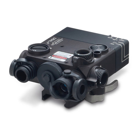
CHAPTER 2- - E QUIPMENT DESCRIPTION 2.1 SYSTEM DESCRIPTION The DBAL-I is a Class IIIa laser device that features an IR POINT and IR ILLUM for use with a NVD. The IR beams can be operated individually or in combina- tion, in both low power (LO PWR) and high power (HI PWR) settings. - Page 14 Figure 2-1 DBAL-I Features ITEM DESCRIPTION IR ILLUM Adjusters IR ILLUM Laser Exit Port 3V CR123A Battery Cap and Compartment IR POINT Laser Exit Port Quick Release Mount IR POINT Adjusters...
- Page 15 2.2 GENERAL CHARACTERISTICS Table 2.2 Weight, Dimensions, and Performance WEIGHT (with one battery, 3-volt CR123A) 8 oz / 226.7 grams DIMENSIONS Length 3.5 in. / 8.9 cm Width 2.75 in. / 7 cm Height (including mounting bracket) 1.59 in. / 4.0 cm PERFORMANCE Laser Wavelength IR POINT...
- Page 16 2.3 DESCRIPTION OF MAJOR COMPONENTS Fig. 2-2 DBAL-I Major Components ITEM DESCRIPTION Tape Fastener Loop 5/8" (Black) Tape Fastener Hook 1/2" (attached to remote cable switch) (Black) Remote Cable Switch, 7" Optical Instrument Reticle (OIR) (set of 5) Battery, 3V CR 123A (must be used with associated battery cap) DBAL-I Assembly Plastic Case...
- Page 17 2.3.a Tape Fastener Loop The Tape Fastener Loop is provided to secure the Remote Cable Switch to the weapon in a position convenient to the soldier. 2.3.b Tape Fastener Hook The Tape Fastener Hook is pre-attached by the manufacturer to the pressure pad switch.
- Page 18 2.3.e Battery One 3V CR 123A battery is used as a power supply for operating the DBAL-I (model dependent). The use of a high-quality battery is recommended. 2.3.f DBAL-I Assembly The DBAL-I device provides an IR POINT and adjustable focus IR ILLUM. The device is used for aiming, signaling, command and control, and for purposes of supplying supplemental IR illumination.
-
Page 19: Section I Operating Instructions
CHAPTER III SECTION I OPERATING INSTRUCTIONS 3.2 DBAL-I CONTROLS AND INDICATORS 3.2.a Battery Installation NOTE Loss or removal of the O-ring from the battery cap may allow water to enter the DBAL-I Unscrew the battery cap in a CW direction. Remove and properly discard the spent battery. - Page 20 Figure 3-1 Battery Installation 3.2.b Activation Mode Selector Switch WARNING The High Power Modes of operation are blocked with a blue Safety Screw. NOTE The DBAL-I will not operate if the rotary switch is not aligned with the marked switch position. In extreme cold temperatures the switch may offer more resistance.
- Page 21 The Activation Mode Selector Switch is located on the left rear of the DBAL-I housing. It is used to select between the various modes of operation when the Remote Cable Switch or the Integrated Momentary Activation Switch is depressed. The Activation Mode Selector Switch has six positions. See Table 3-1.
- Page 22 Table 3-1 Activation and Mode Selector Switch Functions Switch Marking Remarks Position The DBAL-I will not operate LOW IR POINT is activated Used for bore sighting and (AIM LO) when the Remote Cable training Switch or Integrated Momentary Activation switch is depressed.
- Page 23 3.2.c Safety Screw To operate the DBAL-I in the High Power modes, the blue Safety Screw must be removed from the back of the unit. The Armorer will remove and store the Safety Screw. CAUTION DO NOT over tighten the Safety Screw when installing it into the DBAL-I housing as you may strip the housing threads.
- Page 24 3.2.d Integrated Momentary Activation Switch The Integrated Momentary Activation Switch is located on the top of the DBAL-I housing below the word FIRE. Firmly pressing and holding the switch activates the DBAL-I laser function selected by the Activation Mode Selector Switch.
- Page 25 3.2.e Activation Indicator A green LED is located on the rear housing between the Activation Mode Selector Switch and the remote cable receptacle. When lit, it indicates that the DBAL-I is actively emitting laser energy. It also acts as a Low Battery Indicator. When the Activation Mode Selector Switch is turned to an operating position, the LED will light up if either the Remote Cable Switch or Integrated Momentary Activation Switch is pressed and held, indicating that the laser is ON.
- Page 26 Figure 3.5 Laser Activation/Low Battery LED 3.2.f Remote Cable Switch CAUTION DO NOT remove the Remote Cable Switch by pulling on the cable. NOTE When installing the Remote Cable Switch, twist the plug into the remote cable port. The DBAL-I Activation Mode Selector Switch must be turned to a laser setting to use the Remote Cable Switch.
- Page 27 The Remote Cable Switch plugs into the back of the DBAL-I for weapon mounted use as shown in Figure 3-6. Pressing the Remote Cable Switch activates the DBAL-I in the operational mode and power level selected by the Activation Mode Selector Switch (e.g. A/L, D/L, A/H, etc). When the remote cable switch is released, the DBAL-I turns off.
- Page 28 3.2.g IR ILLUM Focusing Knob CAUTION Prior to submerging the DBAL-I make sure the infrared illuminator focusing knob has been adjusted in a CCW direction to its stop. To prevent damage to the IR ILLUM Exit Port Cover, open the Exit Port Cover before turning the knob to adjust the focus.
- Page 29 Focus Focus IR ILLUM Focusing Knob Figure 3-7 The IR ILLUM Focusing Knob 3.2.h Optical Instrument Reticles (OIR) (Pattern Generators) NOTE OIRs are not designed for accurate aiming of the weapon. Exit port covers are not intended for use over the Optical Instrument Reticles. When installing the OIR, the top loop is identified by an “ear”...
- Page 30 The Optical Instrument Reticles (OIR), or Pattern Generators, are used for command and control. When an OIR is installed in front of the IR ILLUM that has been focused to a spot, it will project the shape of a circle, triangle, plus sign, square, or T-shape as shown in Figure 3-8.
- Page 31 To install the OIR, stretch the end of the retaining strap over the retaining stud located on the bottom of the housing. Repeat the procedure by stretching the loose end of the retaining strap over the stud located on the top of the housing. Figure 3-9 Installation of OIR, or Pattern Generator CAUTION DO NOT over adjust the adjusters by forcing them beyond their end of travel.
- Page 32 3.2.I Adjusters The adjuster may offer resistance as you turn it in a CW direction from the factory neutral position. When the adjuster is harder to turn, it has reached the maximum CW travel. When the adjuster is at its maximum CW or CCW point of travel and turned in the opposite direction, the laser point may trace a small loop on the target.
- Page 33 on the same side of the target as the laser is mounted and must fall within 15 cm of the bore at 25 meters. See Paragraph 3.6. The DBAL-I is equipped with adjusters to zero the IR POINT and IR ILLUM. Each adjuster click will move the laser point by 1 cm at 25 meters.
- Page 34 IR ILLUM Adjusters Aiming Beam Adjusters Figure 3-10 Adjusters for Figure 3-11 Adjusters for Illumination Beam Aiming Beam Figure 3-12 Adjuster Guard Markings...
- Page 35 Aiming Laser Adjustment Table 3-2 indicates the direction of adjuster rotation and shot group movement for zeroing the IR POINT to the weapon when the DBAL-I Top Mounted. Figure 3-13 IR POINT Adjusters (Top Mounted)
- Page 36 Table 3-2 Adjuster Rotation and Shot Group Movement for the Aiming Lasers (Top Mounted) ZEROING THE AIMING LASER Adjuster Movement Shot Group Movement Top Adjuster Elevation (guard marked U/D) Down Side Adjuster Windage Right (guard marked R/L) Left When adjusting in a CCW direction, apply a positive load to the adjuster by turning an additional 1/4 turn (12 clicks) CCW, then make the final adjustments by turning the adjusters in a CW direction.
- Page 37 Figure 3-14 IR ILLUM Adjusters (Right Mounted) Table 3-3 Adjuster Rotation and Illumination Area Movement for the IR ILLUM (Right Mounted) ZEROING THE IR ILLUM Adjuster Movement Shot Group Movement Top Adjuster Elevation (guard marked U/D) Down Side Adjuster Windage Left (guard marked L/R) Right...
-
Page 38: Section Ii Mounting Procedures
CHAPTER III SECTION II MOUNTING PROCEDURES 3.3 MOUNTING PROCEDURES WARNING Be sure the weapon is CLEAR and on SAFE before proceeding. NOTE The DBAL-I may be placed at any position (forward and aft) on the rail that is convenient for the operator. If the DBAL-I is removed from the rail, the operator must take note of the position at which it was zeroed, and return it to the same position in order to ensure that zero is retained. - Page 39 An integrated Quick Release Mount is used to attach the DBAL-I to weapons equipped with a MIL-STD-1913 rail. Place the unit far enough back on the rail to allow for battery replacement without removal from the weapon. If removed, the DBAL-I must be returned to the same position on the rail to retain zero.
- Page 40 3.3.a M4/M16A4 Mounting Procedure WARNING Be sure the weapon is CLEAR and on SAFE before proceeding. NOTE The DBAL-I may be placed at any position (forward and aft) on the rail that is convenient for the operator. If the DBAL-I is removed from the rail, the operator must take note of the position at which it was zeroed, and return it to the same position in order to ensure that zero is retained.
- Page 41 Figure 3-12 DBAL-I Top Mounted on M4/M16A The DBAL-I may be mounted on the Top, Left, or Right rail using the Quick Release Mount. Open the Quick Release Mount so that it is perpendicular to the DBAL-I housing. See Figure 3-15. Align the crossbar on the bottom of the mount with a slot on the rail.
- Page 42 CHAPTER III SECTION III ZEROING PROCEDURES This section provides zeroing instructions for the DBAL-I using the AA Borelight System, Item No. 9090 3.4 PLACING A POSITIVE LOAD ON THE ADJUSTERS CAUTION DO NOT over-adjust the adjusters by forcing them beyond their end of travel. NOTE ALWAYS Zero starting with the Adjuster marked U/D.
- Page 43 When adjusting in a CCW direction, apply a positive load to the adjuster by turning an additional turn (8 clicks) CCW, then make the final boresight/zero adjustment by turning the adjuster CW. For example, to move the adjuster one (1) click CCW, turn the adjuster CCW 8 clicks and then turn it CW 7 clicks to the new position.
- Page 44 The DBAL-I is preset at the factory to a neutral position. In the neutral position the laser beam is parallel to the bore of the weapon. The IR POINT can be returned to the factory alignment (neutral position) using the following procedure: 1.
- Page 45 Table 3-4 Factory Neutral Preset Adjuster Instruction Adjuster Guard marked U/D First, turn CW to end of travel. DO NOT for the IR POINT force past mechanical stop. Next, turn CCW 1 turns. Finally, turn CW to Adjuster Guard marked R/L for the align the dot on the adjuster with the IR POINT dot on the adjuster guard.
- Page 46 Table 3-5 DBAL-I Mounting Configurations and Weapon Offsets Weapon Mount Range 10m Boresight Target 25m Target Zero Offset Offset Squares to Strike Point M4 / M16A4 Top Rail 300m IR ILLUM 2.1R / 2.9U IR ILLUM 2.1L / 0.0 IR POINT 1.9R / 3.0U IR POINT 1.9L / 0.0...
- Page 47 Table 3-5 DBAL-I Mounting Configurations and Weapon Offsets, continued Weapon Mount Range 10m Boresight Target 25m Target Zero Offset Offset Squares to Strike Point M249 Short Barrel Right Rail 400m IR ILLUM 4.3R / 7.5D IR ILLUM 2.1R / 4.4U IR POINT 4.3R / 7.0D IR POINT...
- Page 48 3.6.a Boresight Using the Laser Borelight System WARNING NEVER boresight in the High Power mode of operation. CAUTION DO NOT over-adjust the adjusters by forcing them beyond their end of travel. NOTE Always move the adjusters slowly, one click at a time, to prevent the adjuster from jumping detents.
- Page 49 The adjuster knobs on the DBAL-I may vary slightly in the force required to turn the adjusters. This is normal and does not indicate a failure condition. At the maximum CW or CCW travel the DBAL-I lasers may not move a full 1 cm per click at 25 m, or may jump squares on the target.
-
Page 50: Section Iii Zeroing Procedures
3. Stabilize the weapon so it does not move and insert the Borelight Arbor assembly into the muzzle of the weapon. 4. Activate the Borelight and verify that the Borelight is properly aligned. Refer to LBS Operator’s Manual for zeroing procedures. 5. - Page 51 Figure 3-14 Laser Borelight 10 meter Zeroing Target...
- Page 52 3.6.a Zeroing on a 25-Meter Range CAUTION DO NOT over-adjust the adjusters by forcing them beyond their end of travel. NOTE ALWAYS Zero the laser starting with the Adjuster marked U/D. Always move the adjusters slowly, one click at a time, to prevent the adjuster from jumping detents.
- Page 53 The adjuster knobs on the DBAL-I may vary slightly in the force required to turn the adjusters. This is normal and does not indicate a failure condition. At the maximum CW or CCW travel the DBAL-I lasers may not move a full 1 cm per click, or may jump squares on the target.
- Page 54 3. Set the DBAL-I adjusters to their factory neutral position as described in Paragraph 3.5. 4. Activate the IR POINT to be zeroed by rotating the Activation Mode Selector Switch to the desired position. Double-click the Integrated Momentary Acti- vation Switch or the Remote Cable to activate the laser continuously. When aligning the IR POINT, leave the IR/ILLUM Exit Port Cover in place.
- Page 55 Figure 3-15 Commercial 25 meter Zeroing Target...
- Page 56 CHAPTER IV SECTION I PREVENTIVE MAINTENANCE CHECKS 4.1 GENERAL NOTE Table 4-1 Preventive Maintenance Checks, has been provided so that you can keep your equipment in good operating condition. Perform functional tests in the order listed in Table 4-1. Operating Procedures are detailed in Chapter III, Section I.
- Page 57 4.1.b Explanation of Table Entries 1. Item Number Numbers in this column are for reference. Item numbers also appear in the order that you must perform the checks and services listed. 2. Interval This column tells you when you must do the procedure in the procedure column.
- Page 58 Table 4-1 Preventive Maintenance Checks and Services Item Item to Not Fully Mission No. Interval Check/Service Procedure Capable If: B/D/A DBAL-I Exterior -Check housing for A gap appears between separation between the the front and the rear front and the rear section section of the housing, of the housing, missing missing switch knob,...
- Page 59 Table 4-1 Preventive Maintenance Checks and Services Item Item to Not Fully Mission No. Interval Check/Service Procedure Capable If: B/D/A Quick Release -Check attachment to housing, Quick release mount Mount broken, missing parts. loose, missing parts -Inspect rail clamp, crossbar or broken. and mount base for dirt and corrosion.
- Page 60 Table 4-1 Preventive Maintenance Checks and Services Item Item to Not Fully Mission No. Interval Check/Service Procedure Capable If: Activation Mode -Select A/L (AIM LO) using Activation Mode Selector Switch the Activation Mode Selector Switch and Integrated Selector Switch. inoperative with the Momentary -Use the Integrated IR POINT or IR ILLUM...
- Page 61 Table 4-1 Preventive Maintenance Checks and Services Item Item to Not Fully Mission No. Interval Check/Service Procedure Capable If: Remote Cable -Insert the remote cable Switch switch and activate the laser. Flood Adjuster -Check that IR ILLUM adjusts from spot to flood setting.
- Page 62 CHAPTER IV SECTION II TROUBLESHOOTING 4.2 GENERAL The purpose of troubleshooting is to identify the most frequent equipment malfunctions, probable causes, and corrective actions required. Table 4-2 lists the common malfunctions which may be found during the operation or mainte- nance of the DBAL-I and accessory equipment.
- Page 63 Table 4-1 Preventive Maintenance Checks and Services Malfunction Test / Inspection Corrective Action Ref. Para. 1. POINT/ILLUM e. Inspect battery contact spring -Notify Unit Maintenance. beams fail to come in the battery compartment for on or stay on. damage or corrosion. f.
- Page 64 Table 4-1 Preventive Maintenance Checks and Services Malfunction Test / Inspection Corrective Action Ref. Para. 5. POINT beam a. Verify Quick Release Mount is -Properly position and cannot be zeroed properly positioned/secured secure. to weapon. to weapon. b. If laser is loose on rail: -Move to different position on rail.
-
Page 65: Section Iii Operator Maintenance
CHAPTER IV SECTION III OPERATOR MAINTENANCE 4.3 GENERAL WARNING DO NOT store the DBAL-I with the battery installed. CAUTION The use of gun cleaning agents that contain perchloroethylene or methylene chloride may permanently damage the DBAL-I system. The DBAL-I is a rugged, compact laser device that is designed to operate in severe military environments. - Page 66 4.3.a External Cleaning Clean the exterior of the DBAL-I by flushing with water and wiping with a clean, soft cloth. Cleaning should be done whenever the DBAL-I becomes dirty or after exposure to salt water. 4.3.b Exit Port Lens Cleaning To clean the POINT and ILLUM Exit Port Lenses, wipe clean using a soft cloth or disposable applicator dampened with water.
- Page 67 4.3.f Battery Removal and Replacement Refer to Chapter III, Paragraph 3.2.a for Battery Installation procedures. No special tools or equipment are required to replace the battery. 4.3.g Replace Remote Cable Before each use, inspect the remote cable port for dirt, dust, or corrosion. Thoroughly clean the receptacle by flushing with water, then wipe with a soft cloth or disposable applicator.
- Page 68 3. If possible, wash your hands prior to greasing the O-ring. Lubricate the O-ring using your fingertips and a small amount of silicone grease until there is a thin film covering the complete surface. DO NOT stretch the O-ring. 4. Before replacing the O-ring, visually inspect the groove in the battery compartment cap for hair, sand, lint, or other debris and wipe clean as necessary.
-
Page 69: Section I Unit Troubleshooting
CHAPTER V SECTION I UNIT TROUBLESHOOTING 5.1 GENERAL Troubleshooting will identify equipment malfunctions, probable causes and corrective actions. Table 5-1 lists common malfunctions that may occur. Perform the tests in the order they are listed. Table 5-1 Unit Troubleshooting Malfunction Test / Inspection Corrective Action Ref. - Page 70 Table 5-1 Unit Troubleshooting Malfunction Test / Inspection Corrective Action Ref. Para. 3. Beams do not a. Verify adjuster function. -Clean as required. 5.2.a move. -Return for repair. 5.6.a 4. Remote Cable a. Inspect Remote Cable Port -Clean remote cable port 5.2.f Switch inoperable, for dirt or debris.
-
Page 71: Section Ii Unit Maintenance
CHAPTER V SECTION II UNIT MAINTENANCE 5.2 GENERAL CAUTION The use of gun cleaning agents that contain perchloroethylene or methylene chloride may permanently damage the DBAL-I system. Unit Maintenance Procedures consist of operational tests, inspections, troubleshooting and the replacement of a limited number of parts (paragraphs 5.2.a through 5.2.g). - Page 72 clean cloth. If a damp cloth is used to clean the battery compartment make sure to allow the compartment to air dry completely before reinstalling the battery cap. 5.2.d Battery Cap Prior to water operations or immersion, inspect the O-ring and the battery cap to make sure they are free of dirt, moisture or corrosion.
- Page 73 5.3 TESTS AND INSPECTIONS See Preventive Maintenance Checks and Services Table 4-1. 5.4 REMOVAL AND REPLACEMENT OF PARTS Unit Maintenance is authorized for the removal and replacement of a limited number of assemblies. All repair parts can be installed at the unit level. Special tools or equipment are not required for maintaining the DBAL-I 5.4.a Battery Removal and Installation See Chapter III, Paragraph 3.2.a for procedures.
- Page 74 To install, stretch the end of the retaining strap over the stud located on the battery cap. Stretch the other end of the strap over the stud located below the IR ILLUM focusing assembly. To remove, stretch the end of the Strap over the stud on the Battery Cap then stretch the other end over the stud below the IR ILLUM.
- Page 75 CAUTION DO NOT over tighten the Safety Screw as it may strip the threads in the housing. The Armorer will remove and store the Safety Screw using a 3/32 in. hex key. The Armorer will install the Safety Screw using a 3/32 in. hex key. 5.4.f Removal and Replacement of Exit Port Cover Retaining Straps To remove the top Exit Port Cover, pull on the loose end of the Exit Port Cover retaining strap and stretch it over the top stud.
-
Page 76: Section Iii Service/Packing And Unpacking
CHAPTER V SERVICE/PACKING AND UNPACKING 5.5 Steiner 3-Year Laser Device Warranty On all laser devices, Steiner offers a 3-Year Limited Warranty from the date of purchase that covers all laser, optical and electronic components, materials and workmanship. All warranties are void if the serial number or manufacturer’s... - Page 77 If Steiner determines that the item is under warranty or should be returned for repair, a Return Material Authorization (RMA) number will be provided. 5.6.c When returning the DBAL-I for service or repair, the following procedures should be followed to prevent any additional damage: 1.
-
Page 78: Repair Parts
APPENDIX A REPAIR PARTS Figure 1 Repair Parts... - Page 79 Table A-1 Repair Parts List Item No. Description Remote Cable Switch, 7" Loop Tape Battery Cap Strap, Battery Cap Bag, Textile Assy, DBAL-I Safety Screw, Hexagon Head O-Ring Assembly, Dust Cover, Clam Assembly, 80° Diffuser...
- Page 80 STEINER-OPTIK 331 East 8th Street • Greeley, CO 80631 Tel: (888) 228-7747 • Fax: (970) 356-8702 Customer Service: laserlightsinfo@steiner-optics.com steiner-optics.com...
Need help?
Do you have a question about the DBAL-I2 and is the answer not in the manual?
Questions and answers