Table of Contents
Advertisement
Quick Links
Advertisement
Table of Contents

Related Manuals for XtendLan EBF-231-5I24


Summary of Contents for XtendLan EBF-231-5I24
- Page 1 EBF-231-5I24 Embedded PC User’s Guide...
- Page 2 Safety Instructions Please read this manual carefully before using the product; Before inserting, removing or re-configuring motherboards or expansion cards, first disconnect the computer and peripherals from their power sources to prevent electric shock to human bodies or damage to the product; Before moving the product, please unplug the AC cable from the power socket;...
-
Page 3: Table Of Contents
C o n t e n t s Chapter 1 Product Introduction ..................4 Overview.......................... 4 Main Function ........................4 Main Performance ......................6 Mounting Mode ....................... 7 Requirements of Transportation and Storage ..............8 Chapter 2 Installation ....................... 9 Product Outline ........................ -
Page 4: Chapter 1 Product Introduction
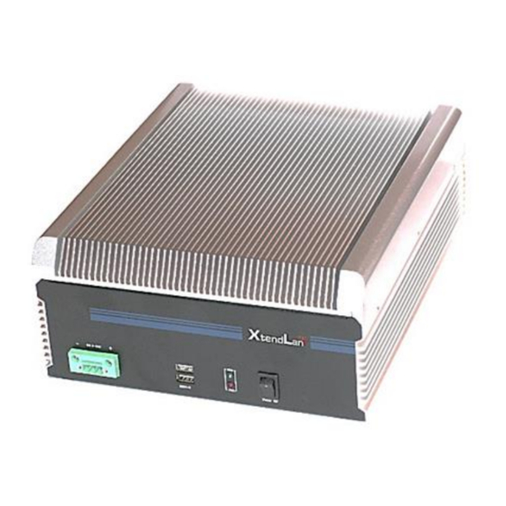
Chapter 1 Product Introduction Overview EBF-231-5I24 is a high performance low power fanless embedded box PC. The product features al-alloy chassis, small form factor, compact and rugged structure, as well as fanless design. The PC dissipates heat from the shell, and provides excellent dust-proof, heat dissipation and anti-vibration performance. - Page 5 800/1066MHz. The PC provides a single 2G memory bank as standard configuration. Network Function Provides two 10/100/1000Mbps LAN ports; LAN1 supports Wake-on-LAN, LAN PXE booting and AMT6.0 functions. Display Function Adopts Intel® Arrandale CPU built-in integrated graphic controller display chip;...
-
Page 6: Main Performance
Storage Device Provides one 2.5″ 250G hard disk as standard configuration; Power Feature The PC provides one built-in DC-DC wide-voltage input power module as well as AC-DC adapter in standard configuration. ① PC DC wide voltage input feature. Input Voltage/Frequency: 9 ~ 36V DC. ②... -
Page 7: Mounting Mode
Storage Environment: Temperature: -30°C ~ 65°C; Humidity: 5% ~ 90% (non-condensing); GB9254-1998 Radiation susceptibility class A, Conducted disturbance class A; GB/T 17626.2.2006 Electrostatic discharge, level 2; GB/T 17626.3-2006 Burst immunity, level 2; GB/T 17626.5-2008 Surge (Impact) immunity, level 2; ... -
Page 8: Requirements Of Transportation And Storage
Requirements of Transportation and Storage Transportation Well-packaged products are suited for transportation by truck, ship, and plane. During transportation, products should not be put in open cabin or carriage. When transshipping en route, products should not be stored in open air without protection from the atmospheric conditions. -
Page 9: Chapter 2 Installation
Chapter 2 Installation Product Outline... -
Page 10: Product Appearance And Installation Dimensions
Product Appearance and Installation Dimensions Unit: mm - 10... -
Page 11: External Connectors
External Connectors Front Panel 1. DC-IN 2. USB 1/2 3. Power Indicator 4. Switch 5. HDD Indicator 5 6 7 Rear Panel - 11... -
Page 12: Overall Assembly Drawing
1. HDMI 2. LAN2 3. LAN1 4. VGA 5. Line-in 6. Mic-in 7. Line-out 8. COM1 9. COM2 10. USB 3/4 11. COM3 12. COM4 13. PCI-E Expansion Card 14. Grounding Screw Overall Assembly Drawing - 12... - Page 13 1. Front Panel Module 2. Bottom Cover 3. Mounting Bracket 4. Left Panel of the Chassis 5. Fixing Bar of the Upper Cover 6. I/O Bracket 7. Rear Panel Module 8. Cover 9. Right Panel of the Chassis 10. Power Supporting Board 11.
-
Page 14: Install The Hard Disk
Install the Hard Disk Loosen the screws on the HDD module tray 2 and the HDD module tray 1 via crosshead screwdriver and take off the HDD module. Install the 2.5″ hard disk (Users may install the HDD according to their requirement) into the HDD fixing bracket; make sure the screw holes on both sides of the hard disk are in alignment with the mounting holes on the HDD fixing bracket;... -
Page 15: Install The Pci-E Expansion Card
Install the PCI-E Expansion Card Loosen the screws fixing the slot cover screw bracket and the left side board of the chassis and then take off the slot cover screw bracket. Insert the PCI-E expansion card into the I/O bracket; get the cross head screw driver through the vias on the right side board of the chassis and fix the PCI-E expansion card via truss head screws. -
Page 16: Chapter 3 Install The Drivers
Chapter 3 Install the Drivers Regarding the installation of the driver program, please refer to the CD that accompanies the PC. - 16...
Need help?
Do you have a question about the EBF-231-5I24 and is the answer not in the manual?
Questions and answers