Table of Contents
Advertisement
Quick Links
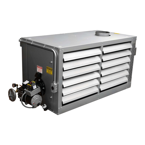
Econo Heater
Manufactured by
Waste Oil Fired Heater
Installation, operation and service instructions
240
EH-350 120v Manual
EconoHeat • 5714 E. First Avenue • Spokane Valley, WA 99212 • 800.255.1363 • www.econoheat.com • Rev 01/2017
Omni Heat NZ * P.O Box 112 Cromwell 9342 * 32 Ree Crescent Cromwell 9310 * 027 203 2121 * www.omniheat.co.nz
Advertisement
Table of Contents

Related Manuals for Econo Heat OMNI EH-350


Summary of Contents for Econo Heat OMNI EH-350
- Page 1 Econo Heater Manufactured by Waste Oil Fired Heater Installation, operation and service instructions EH-350 120v Manual EconoHeat • 5714 E. First Avenue • Spokane Valley, WA 99212 • 800.255.1363 • www.econoheat.com • Rev 01/2017 Omni Heat NZ * P.O Box 112 Cromwell 9342 * 32 Ree Crescent Cromwell 9310 * 027 203 2121 * www.omniheat.co.nz...
-
Page 2: Table Of Contents
Table of Contents Precautions ................... Page 3 Important Notice ................. Page 4 Speciications ................Page 5 Installation Procedures .............. Page 6 Stack Installation ................Page 7 Oil Supply Tubing ................. Page 7 Wiring ....................Page 8 Oil Burner ..................Page 9 Oil Burner Technology .............. -
Page 3: Precautions
PR ECAUTION S Waste oil may contain many foreign materials. Waste oil may also contain gasoline. Therefore, speciic precautions on the handling and storage of waste oils are to be observed when using, cleaning, and maintaining this heater. Use a screen in a funnel when pouring oil into storage tank to catch foreign material, i.e., gasket material and sealant ibers, etc. -
Page 4: Important Notice
IMPOR TANT Notice to the owner and installer To enjoy the long-term beneits of burning your used oil in an EconoHeat Waste Oil Burning appliance, it is necessary to become familiar with the correct installation operation and maintenance of your new furnace. Before installing or operating this appliance, make sure you read and understand this manual. -
Page 5: Speciications
Speciications BTU INPUT: 350,000 BTU OUTPUT: 300,000 GALLONS PER HOUR: REQUIRED VOLTS: AMPs FULL LOAD: 18.7 FAN MOTOR HP: 2 @ 1/4 each FAN MOTOR RPM: 1075 CFM (FREE AIR): 6275 CFM w/ DUCTWORK @ 100 ft.: 1600 EFFECTIVE AIR FLOW: 80 ft FLUE SIZE: 8"... -
Page 6: Installation Procedures
Installation Procedures 8” stack 1/2 - 3/4 ID copper tubing Figure 1 – Installation Diagram EconoHeater by EconoHeat Page 6... -
Page 7: Stack Installation
Stack Installation 1. Install a barometric damper (NOT included) in the stack if the draft up the stack exceeds -.08. Draft up the stack must be minimum -.04 to -.06 inches of water column. Check with draft meter 12” from the top of the heater in (stack) or lue pipe. The over ire draft should be a minimum of -.02- check through lame inspection port. -
Page 8: Wiring
Wiring Figure 2 – Wiring Diagram 1. Wire 120V into main electrical box mounted on burner backside of heater cabinet with separate circuit 20-amp protection using 12-gauge wire. Connect power line to black wire and all whites (NEUTRAL or COMMON) together. IMPORTANT, Connect ground wire to ground mounting point in main junction box (green screw). -
Page 9: Oil Burner
Oil Burner WARNING Installation and use of this used oil burning appliance shall be in accordance with the standard for the Installation of Oil Burning Equipment – ANSI/NFPA 31 – 1987, and National Electric Code – ANSI/NFPA 70 – 1990 and the requirements of the inspection authorities having jurisdiction. -
Page 10: Oil Burner Technology
This pressure system is 150-200 psi and has the ability to control lame even when various viscosities are used- furnace or stove oil to 90 weight straight- lame remains stable Transformer Oil Primary Photo Eye/Flame Sensor (CAD Cell) Flame Cone Solenoid Valve Electrodes Nozzle... - Page 11 Burner Components • Igniter Transformer: (igure 3) Supplies high voltage to the electrodes generating electrical arc igniting the oil. • Oil Valve: (igure 3) energizes when burner is running and de-energizes when burner is not running eliminating bleed back of oil out of the Pre-heater block. •...
-
Page 12: Initial Start Procedure
Initial Start Procedure 1. IMPORTANT – Prior to starting the unit, pre-ill the ilter and fuel line with oil to assist priming procedure. Make sure the oil supply line ittings are air tight. Vacuum leaks are notoriously hard to ind. Pressurizing the line with oil in it can help to locate leaks. 2. -
Page 13: Maintenance Schedule
Suggested Maintenance Schedule Every application varies. Monitor your needed schedules. WEEKLY • Drain water from storage tank. MONTHLY • Check your ash accumulation for best performance, remove if excessive (the size of unit, type of oil and run time are all contingent factors). •... -
Page 14: Figures
ELECTRODE ADJUSTMENTS Electrodes are adjusted at time of manufacture. However, they should be checked periodically and at time of installation, to be sure they are set as noted in the following dimensional drawing. Swing burner clean out door back for inspection (igures 8 and 10 below). CAUTION: TURN OFF MAIN ELECTRIC SUPPLY SWITCH BEFORE CHECKING OR ADJUSTING ELECTRODE SETTING. - Page 15 When cleaning, inspect all three pieces thoroughly. When disassembling and reassembling nozzle, keep facing up as shown. Figure 7 – Nozzle Assembly Detail Figure 8 – Electrode Adjustment Detail Thermocouple Pre Heater Oil Block Electrodes Pre-Heater Control Board Nozzle Figure 9 – Pre-Heater Block Detail (Removed From Burner for Clarity) EconoHeater by EconoHeat Page 15...
- Page 16 Remove 4 bolts for access to strainer ilter. CAUTION: must be careful not to destroy the inner gasket during removal of the housing. Figure 10 – Pump Strainer Figure 11 – Oil Filter (Pancake Style Filter) EconoHeater by EconoHeat Page 16...
-
Page 17: Troubleshooting
Troubleshooting EconoHeater by EconoHeat Page 17... -
Page 18: Eh-350 Ten Year Limited Warranty
Troubleshooting Continued EH-350 Ten (10) Year Limited Warranty EconoHeat (manufacturer) warrants to the purchaser of Unit Heaters listed above will be free from defects in materials and workmanship for the durations speciied below, which duration begins on the date of delivery to the customer. Customer is responsible for maintaining proof of date of delivery. - Page 19 EH-350 Ten (10) Year Limited Warranty Cont. This warranty is void if: • Warranty registration card is not returned within sixty (60) days of purchase • Any part or component subject to abuse or altered from original manufactures speciications • Installation not in accordance with instructions •...
-
Page 20: Warranty Card
Warranty Card Please fill out, tear off and return to manufacturer within sixty (60) days of purchase, or warranty will not be valid. Please print or type. Date of Purchase: Serial #: Model #: Customer (Company) Name: Address: City: State: Zip Code: Dealer: Address:...
Need help?
Do you have a question about the OMNI EH-350 and is the answer not in the manual?
Questions and answers