Table of Contents
Advertisement
Quick Links
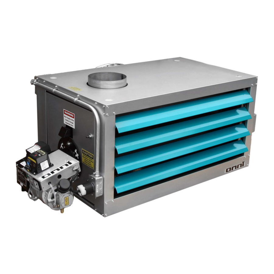
Waste Oil Fired Heater
Installation, operation and service instructions
240 V
OWH-150 120v Manual
EconoHeat • 5714 E. First Avenue • Spokane Valley, WA 99212 • 800.255.1363 • www.econoheat.com • Rev 01/2017
Omni Heat NZ * P.O Box 112 Cromwell 9342 * 32 Ree Crescent Cromwell 9310 * 027 203 2121 * www.omniheat.co.nz
Advertisement
Table of Contents

Subscribe to Our Youtube Channel
Related Manuals for Econo Heat OMNI OWH-150


Summary of Contents for Econo Heat OMNI OWH-150
- Page 1 Waste Oil Fired Heater Installation, operation and service instructions 240 V OWH-150 120v Manual EconoHeat • 5714 E. First Avenue • Spokane Valley, WA 99212 • 800.255.1363 • www.econoheat.com • Rev 01/2017 Omni Heat NZ * P.O Box 112 Cromwell 9342 * 32 Ree Crescent Cromwell 9310 * 027 203 2121 * www.omniheat.co.nz...
-
Page 2: Table Of Contents
Table of Contents Precautions ................... Page 3 Important Notice ................. Page 4 Speciications ................Page 5 Installation Procedures .............. Page 6 Stack Installation ................Page 7 Oil Supply Tubing ................. Page 7 Wiring ....................Page 8 Ducting ................... Page 8 Oil Burner .................. -
Page 3: Precautions
PR ECAUTION S Waste oil may contain many foreign materials. Waste oil may also contain gasoline. Therefore, speciic precautions on the handling and storage of waste oils are to be observed when using, cleaning, and maintaining this heater. Use a screen in a funnel when pouring oil into storage tank to catch foreign material, i.e., gasket material and sealant ibers, etc. -
Page 4: Important Notice
IMPOR TANT Notice to the owner and installer To enjoy the long-term beneits of burning your used oil in an OMNI Waste Oil Burning appliance, it is necessary to become familiar with the correct installation operation and maintenance of your new furnace. Before installing or operating this appliance, make sure you read and understand this manual. -
Page 5: Speciications
Speciications BTU INPUT: 150,000 BTU OUTPUT: 120,000 GALLONS PER HOUR: REQUIRED VOLTS: AMPs FULL LOAD: 14.6 FAN MOTOR HP: FAN MOTOR RPM: 1075 CFM (FREE AIR): 3762 CFM w/ DUCTWORK @ 100 ft.: 1380 EFFECTIVE AIR FLOW: 60 ft FLUE SIZE: 8"... -
Page 6: Installation Procedures
Installation Procedures Figure 1 – Installation Diagram OMNI by EconoHeat Page 6... -
Page 7: Stack Installation
Stack Installation 1. Install a barometric damper (NOT included) in the stack if the draft up the stack exceeds -.08. Draft up the stack must be -.04 to -.06 inches of water column. Check with draft meter between the top of the heater and damper. The over ire draft should be a minimum of -.02- check through lame inspection port. -
Page 8: Wiring
Wiring Figure 2 – Wiring Diagram 240 V 1. Wire 120V into main electrical box mounted on burner backside of heater cabinet with separate circuit 20-amp protection using 12-gauge wire. Connect power line to black wire and all whites (NEUTRAL or COMMON) together. IMPORTANT, Connect ground wire to ground mounting point in main junction box (green screw). -
Page 9: Oil Burner
Oil Burner WARNING Installation and use of this used oil burning appliance shall be in accordance with the standard for the Installation of Oil Burning Equipment – ANSI/NFPA 31 – 1987, and National Electric Code – ANSI/NFPA 70 – 1990 and the requirements of the inspection authorities having jurisdiction. - Page 10 Mounting Flange (3 or 4 bolt universal pattern) Vanes/Carbon Plate (Remove Cover) Electrodes Nozzle Oil Valve Burner Motor Flame Cone Compressor Figure 5 – Oil Burner (Front View) Oil Primer Switch Inline Breaker Oil Outlet Oil Inlet Filter Figure 6 – Oil Pump Diagram OMNI by EconoHeat Page 10...
-
Page 11: Oil Burner Technology
Oil Flow Control Supply Pump has the ability to control lame even when various viscosities are used- furnace or stove oil to 90 weight straight- lame remains stable Oil Shut-off Valve Inline Breaker Oil Primer Switch (Eliminates start delays due (Solenoid valve, on/off) to possible drain back) Adjustable... - Page 12 Burner Components • Igniter Transformer: (igure 3) Supplies high voltage to the electrodes generating electrical arc igniting the oil. • Oil Valve: (igure 5) energizes when burner is running and de-energizes when burner is not running eliminating bleed back of oil out of the Pre-heater block. •...
-
Page 13: Initial Start Procedure
IMPORTANT: • Power Indicator: (igure 3) Indicates when power is present at the burner. • Run Indicator: (igure 3) Indicates that the burner is ready for operation after the initial pre- heat time of approx. 5 minutes from initial power up. Initial Start Procedure 1. -
Page 14: Maintenance Schedule
Maintenance Schedule WEEKLY • Drain water from storage tank. MONTHLY • Check your ash accumulation for best performance, remove if excessive (the size of unit, type of oil and run time are all contingent factors). • Change or Replace Spin-On Filter or Filter screen located in the pancake style housing (igure 14 below). -
Page 15: Figures
IMPORTANT NOTE: be sure nozzle is centered, if nozzle is higher than center, press nozzle down to bottom out pre-heater stand. To adjust, open burner clean out door (igure 8 bleow), loosen Preheat Sink securing nut and set screw, push fore or aft as needed. WARNING: This adjustment is done at the factory and should not be moved unless igure 8 dimensions have been altered. - Page 16 When cleaning, inspect all three pieces thoroughly. When disassembling and reassembling nozzle, keep facing up as shown. Figure 10 – Nozzle Assembly Detail Figure 10 – Electrode Adjustment Detail Thermocouple Snap Switch Pre Heater Oil Block Electrodes Pre-Heater Control Card Nozzle Figure 11 –...
- Page 17 Figure 12 – Combustion Chamber and Heat Exchanger Clean-out Door Remove 4 bolts for access to strainer ilter. CAUTION: must be careful not to destroy the inner gasket during removal of the housing. Figure 14 – Oil Filter (Spin-On Filter above, Figure 13 –...
-
Page 18: Troubleshooting
Troubleshooting ♦Most Likely ♣Least Likely •Less Likely Symptom Cause Remedy ♦ Manual reset ♦ equiring manual restart 1. Heater shuts reset button on. ♦ acuum air leak i ♦ Check all uel connections. Tight 2. Loss prime overnight uel line ittings. -
Page 19: Owh-150 Fifteen Year Limited Warranty
OWH-150 Fifteen (15) Year Limited Warranty EconoHeat (manufacturer) warrants to the purchaser of Unit Heaters listed above will be free from defects in materials and workmanship for the durations speciied below, which duration begins on the date of delivery to the customer. Customer is responsible for maintaining proof of date of delivery. -
Page 20: Warranty Card
NOTE: Combustion Chamber Warranty is speciic to material and workmanship. Workmanship means EconoHeat warranties the welds are good and will hold. Material means they will not corrode through due to sulfur in the ash that accumulates during operation. Warranty does not apply to units that experience overheating stress cracks.
Need help?
Do you have a question about the OMNI OWH-150 and is the answer not in the manual?
Questions and answers