
Subscribe to Our Youtube Channel
Related Manuals for YASKAWA VIPA FM 050-1BS00


Summary of Contents for YASKAWA VIPA FM 050-1BS00
- Page 1 VIPA System SLIO FM | 050-1BS00 | Manual HB300 | FM | 050-1BS00 | en | 20-40 SSI module - FM 050S...
- Page 2 YASKAWA Europe GmbH Ohmstraße 4 91074 Herzogenaurach Tel.: +49 9132 744 0 Fax: +49 9132 744 186 Email: info@yaskawa.eu.com Internet: www.yaskawa.eu.com 050-1BS00_000_FM050S,6,EN - © 2020...
-
Page 3: Table Of Contents
VIPA System SLIO Table of contents Table of contents General........................4 1.1 Copyright © YASKAWA Europe GmbH............4 1.2 About this manual..................... 5 1.3 Safety information..................... 6 Basics and mounting..................... 7 2.1 Safety information for users................7 2.2 System conception................... 8 2.2.1 Overview...................... -
Page 4: General
This material is protected by copyright laws. It may not be reproduced, distributed, or altered in any fashion by any entity (either internal or external to YASKAWA) except in accordance with applicable agreements, contracts or licensing, without the express written consent of YASKAWA and the business management owner of the material. -
Page 5: About This Manual
Tel.: +49 6196 569 500 (hotline) Email: support@yaskawa.eu.com 1.2 About this manual Objective and contents This manual describes the VIPA FM 050-1BS00 of the System SLIO. It contains a description of the construction, project implementation and usage. Product Order number... -
Page 6: Safety Information
VIPA System SLIO General Safety information CAUTION! Damages to property is likely if these warnings are not heeded. Supplementary information and useful tips. 1.3 Safety information Applications conforming The system is constructed and produced for: with specifications communication and process control general control and automation tasks industrial applications operation within the environmental conditions specified in the technical data... -
Page 7: Basics And Mounting
VIPA System SLIO Basics and mounting Safety information for users Basics and mounting 2.1 Safety information for users Handling of electrostatic VIPA modules make use of highly integrated components in MOS-Technology. These sensitive modules components are extremely sensitive to over-voltages that can occur during electrostatic discharges. -
Page 8: System Conception
VIPA System SLIO Basics and mounting System conception > Overview 2.2 System conception 2.2.1 Overview The System SLIO is a modular automation system for assembly on a 35mm mounting rail. By means of the periphery modules with 2, 4, 8 and 16 channels this system may properly be adapted matching to your automation tasks. -
Page 9: Components
VIPA System SLIO Basics and mounting System conception > Components 2.2.2 Components CPU (head module) Bus coupler (head module) Line extension 8x periphery modules 16x periphery modules Accessories CAUTION! Only VIPA modules may be combined. A mixed operation with third-party modules is not allowed! CPU 01xC With the CPU 01xC electronic, input/output components and power supply are integrated... - Page 10 VIPA System SLIO Basics and mounting System conception > Components Bus coupler With a bus coupler bus interface and power module is integrated to one casing. With the bus interface you get access to a subordinated bus system. As head module, via the inte- grated power module for power supply, bus interface and the electronic of the connected periphery modules are supplied.
- Page 11 VIPA System SLIO Basics and mounting System conception > Components 8x periphery modules Each 8x periphery module consists of a terminal and an electronic module. Terminal module Electronic module Terminal module The terminal module serves to carry the electronic module, contains the backplane bus with power supply for the electronic, the DC 24V power section supply and the staircase- shaped terminal for wiring.
-
Page 12: Accessories
VIPA System SLIO Basics and mounting System conception > Accessories Electronic unit The functionality of a 16x periphery module is defined via the terminal block, which is connected to the electronic unit via a secure flap mechanism. In the case of an error you can exchange the defective electronic unit for a functional unit with standing wiring. - Page 13 VIPA System SLIO Basics and mounting System conception > Accessories Bus cover With each head module, to protect the backplane bus connectors, there is a mounted bus cover in the scope of delivery. You have to remove the bus cover of the head module before mounting a System SLIO module.
-
Page 14: Hardware Revision
VIPA System SLIO Basics and mounting Dimensions 2.2.4 Hardware revision Hardware revision on the The hardware revision version is printed on every System SLIO module. front Since a System SLIO 8x periphery module consists of a terminal and electronic module, you will find a hardware revision on each of them. Authoritative for the hardware revision of a System SLIO module is the hardware revi- sion of the electronic module. - Page 15 VIPA System SLIO Basics and mounting Dimensions Dimensions CPU 01x Dimensions bus coupler and line extension slave Dimensions line extension master HB300 | FM | 050-1BS00 | en | 20-40...
- Page 16 VIPA System SLIO Basics and mounting Dimensions Dimensions 8x periphery module Dimensions electronic module Dimensions in mm Dimensions 16x periphery module 76.5 12.9 HB300 | FM | 050-1BS00 | en | 20-40...
-
Page 17: Mounting 8X Periphery Modules
VIPA System SLIO Basics and mounting Mounting 8x periphery modules 2.4 Mounting 8x periphery modules Requirements for UL compliance use – Use for power supply exclusively SELV/PELV power supplies. – The System SLIO must be installed and operated in a housing according to IEC 61010-1 9.3.2 c). - Page 18 Even with an existing coding on the terminal module, you can plug an electronic module without coding. The user is responsible for the correct usage of the coding pins. YASKAWA assumes no liability for incorrectly attached electronic modules or for damages which arise due to incorrect...
- Page 19 VIPA System SLIO Basics and mounting Mounting 8x periphery modules Mounting periphery modules Mount the mounting rail! Please consider that a clearance from the middle of the mounting rail of at least 80mm above and 60mm below, respectively 80mm by deployment of shield bus carriers, exist.
-
Page 20: Mounting 16X Periphery Modules
VIPA System SLIO Basics and mounting Mounting 16x periphery modules After mounting the whole system, to protect the backplane bus connectors at the last module you have to mount the bus cover, now. If the last module is a clamp module, for adaptation the upper part of the bus cover is to be removed. - Page 21 VIPA System SLIO Basics and mounting Mounting 16x periphery modules Electronic unit and ter- Each 16x periphery module consists of an electronic unit and a terminal block. minal block Electronic unit Terminal block To replace an electronic unit, you can push down and pull off the terminal block after releasing the lock.
-
Page 22: Wiring 8X Periphery Modules
VIPA System SLIO Basics and mounting Wiring 8x periphery modules Clack For mounting turn the locking lever of the module upwards until it engages. For mounting place the module to the module installed before and push the module to the mounting rail guided by the strips at the upper and lower side of the module. Turn the locking lever of the periphery module downward, again. - Page 23 VIPA System SLIO Basics and mounting Wiring 8x periphery modules Data 240V AC / 30V DC Cross section 0.08 ... 1.5mm (AWG 28 ... 16) Stripping length 10mm Wiring procedure Pin number at the connector Opening for screwdriver Connection hole for wire Insert a suited screwdriver at an angel into the square opening as shown.
-
Page 24: Wiring 16X Periphery Modules
VIPA System SLIO Basics and mounting Wiring 16x periphery modules Attach the cables with the accordingly stripped cable screen and fix it by the shield clamp with the shield bus. 2.7 Wiring 16x periphery modules Terminal block connectors CAUTION! Do not connect hazardous voltages! If this is not explicitly stated in the corresponding module description, hazardous voltages are not allowed to be connected to the corresponding terminal block! -
Page 25: Wiring Power Modules
VIPA System SLIO Basics and mounting Wiring power modules Insert wire The wiring happens without a tool. Determine according to the casing labelling the connection position. Insert through the round connection hole of the according contact your prepared wire until it stops, so that it is fixed. ð... - Page 26 VIPA System SLIO Basics and mounting Wiring power modules Wiring procedure Pin number at the connector Opening for screwdriver Connection hole for wire Insert a suited screwdriver at an angel into the square opening as shown. Press and hold the screwdriver in the opposite direction to open the contact spring. Insert the stripped end of wire into the round opening.
- Page 27 VIPA System SLIO Basics and mounting Wiring power modules PM - Power module For wires with a core cross-section of 0.08mm up to 1.5mm Pos. Function Type Description not connected DC 24V DC 24V for power section supply GND for power section supply Sys DC 24V DC 24V for electronic section supply not connected...
- Page 28 VIPA System SLIO Basics and mounting Wiring power modules Deployment of the power If the 10A for the power section supply is no longer sufficient, you may use the power modules module with the order number 007-1AB00. So you have also the possibility to define isolated groups.
-
Page 29: Demounting 8X Periphery Modules
VIPA System SLIO Basics and mounting Demounting 8x periphery modules Shield attachment Shield bus carrier Shield bus (10mm x 3mm) Shield clamp Cable shield To attach the shield the mounting of shield bus carriers are necessary. The shield bus carrier (available as accessory) serves to carry the shield bus to connect cable shields. Each System SLIO 8x periphery module has a carrier hole for the shield bus carrier. - Page 30 VIPA System SLIO Basics and mounting Demounting 8x periphery modules Exchange of a periphery Power-off your system. module Remove if exists the wiring of the module. For demounting and exchange of a (head) module or a group of modules, due to mounting reasons you always have to remove the electronic module right beside.
- Page 31 VIPA System SLIO Basics and mounting Demounting 8x periphery modules Plug again the electronic module, which you have removed before. Wire your module. ð Now you can bring your system back into operation. Exchange of a module Power-off your system. group Remove if exists the wiring of the module group.
-
Page 32: Demounting 16X Periphery Modules
VIPA System SLIO Basics and mounting Demounting 16x periphery modules Plug again the electronic module, which you have removed before. Wire your module group. ð Now you can bring your system back into operation. 2.10 Demounting 16x periphery modules Proceeding Exchange of an electronic Power-off your system. - Page 33 VIPA System SLIO Basics and mounting Demounting 16x periphery modules Pull the module. For mounting turn the locking lever of the module to be mounted upwards. To mount the module put it to the gap between the both modules and push it, guided by the stripes at both sides, to the mounting rail.
- Page 34 VIPA System SLIO Basics and mounting Demounting 16x periphery modules Pull the module group forward. For mounting turn all the locking lever of the module group to be mounted upwards. To mount the module group put it to the gap between the both modules and push it, guided by the stripes at both sides, to the mounting rail.
-
Page 35: Easy Maintenance
VIPA System SLIO Basics and mounting Easy Maintenance 2.11 Easy Maintenance Overview Easy Maintenance means the support for adding and removing modules during operation without having to restart the system. Here the following behavior is shown by the example of a CPU: Electronic module is removed –... -
Page 36: Trouble Shooting - Leds
VIPA System SLIO Basics and mounting Trouble shooting - LEDs 2.12 Trouble shooting - LEDs General Each module has the LEDs RUN and MF on its front side. Errors or incorrect modules may be located by means of these LEDs. In the following illustrations flashing LEDs are marked by ☼. -
Page 37: Installation Guidelines
VIPA System SLIO Basics and mounting Installation guidelines 2.13 Installation guidelines General The installation guidelines contain information about the interference free deployment of a PLC system. There is the description of the ways, interference may occur in your PLC, how you can make sure the electromagnetic compatibility (EMC), and how you manage the isolation. - Page 38 VIPA System SLIO Basics and mounting Installation guidelines Proof the correct fixing of the lead isolation. – Data lines must be laid isolated. – Analog lines must be laid isolated. When transmitting signals with small ampli- tudes the one sided laying of the isolation may be favourable. –...
-
Page 39: General Data For The System Slio
VIPA System SLIO Basics and mounting General data for the System SLIO 2.14 General data for the System SLIO Conformity and approval Conformity 2014/35/EU Low-voltage directive 2014/30/EU EMC directive Approval Refer to Technical data Others RoHS 2011/65/EU Restriction of the use of certain hazardous substances in electrical and electronic equipment Protection of persons and device protection Type of protection... - Page 40 VIPA System SLIO Basics and mounting General data for the System SLIO Mounting conditions Mounting place In the control cabinet Mounting position Horizontal and vertical Standard Comment Emitted interference EN 61000-6-4 Class A (Industrial area) Noise immunity EN 61000-6-2 Industrial area zone B EN 61000-4-2 8kV at air discharge (degree of severity 3),...
-
Page 41: Hardware Description
VIPA System SLIO Hardware description Properties Hardware description 3.1 Properties Features 1xSSI for absolute-value encoder with 8...32bit, 125kHz...2MHz Connecting by difference signal (RS422) Clock output for master mode Clock input for listening mode Encoder power supply DC 24V integrated transformer for gray/dual asynchronous encoder evaluation Normalization of the encoder value, this means added bits are removed Interrupt and diagnostics function with µs time stamp... -
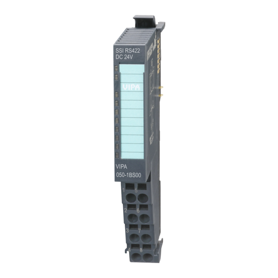
Page 42: Structure
VIPA System SLIO Hardware description Structure 3.2 Structure 050-1BS00 Locking lever terminal module Labeling strip Backplane bus LED status indication DC 24V power section supply Electronic module Terminal module Locking lever electronic module Terminal Status indication Description green Bus communication is OK green Module status is OK Bus communication is OK... - Page 43 VIPA System SLIO Hardware description Structure Pin assignment For wires with a cross section of 0.08mm up to 1.5mm Pos. Function Type Description Clock OUT+ Difference output for Clock OUT (exclusively for master mode) DC 24V DC 24V for encoder Clock IN+ Difference input for Clock IN (exclusively for listening mode) Clock OUT-...
-
Page 44: Technical Data
VIPA System SLIO Hardware description Technical data 3.3 Technical data Order no. 050-1BS00 Type FM 050 Module ID 09C1 7800 Current consumption/power loss Current consumption from backplane bus 85 mA Power loss Parallel switching of outputs for increased power Status information, alarms, diagnostics Status display Interrupts yes, parameterizable... - Page 45 VIPA System SLIO Hardware description Technical data Order no. 050-1BS00 Mode master ü Mode monitoring operation ü Shift direction MSB first ü Shift direction LSB first ü Binary code ü Gray code ü Datasizes Input bytes Output bytes Parameter bytes Diagnostic bytes Housing Material...
-
Page 46: Deployment
VIPA System SLIO Deployment Fast introduction Deployment 4.1 Fast introduction Max. SSI range Limit Valid range of values Lower limit Upper limit 4 294 967 295 (2 1) This value depends on the type of the encoder. Address areas Input area At CPU, PROFIBUS and PROFINET the input area is embedded to the corresponding address area. -
Page 47: In-/Output Area
VIPA System SLIO Deployment In-/Output area > Input area 6byte Name Bytes Function Default CRES reserved 3109h... 310Bh SSI_EN SSI function 310Ch 1) This parameter may only be transferred at STOP state. Encoder evaluation As soon as the module is adapted to the encoder and the parameter SSI function is acti- vated, the module starts with sending the clock signal and evaluating the encoder values. -
Page 48: Parameter Data
VIPA System SLIO Deployment Parameter data 4.3 Parameter data Via parameterization you may define among others: Parameters of the SSI encoder (see data sheet of the encoder) Operating mode of the module (master mode/listening mode) Activation diagnostic interrupt DS - Record set for access via CPU, PROFIBUS and PROFINET IX - Index for access via CANopen SX - Subindex for access via EtherCAT with Index 3100h + EtherCAT-Slot More can be found in the according manual of your bus coupler. - Page 49 VIPA System SLIO Deployment Parameter data Range of values: 0030h = 1µs 0300h = 16µs 0060h = 2µs 0600h = 32µs 00C0h = 4µs 0900h = 48µs 0180h = 8µs 0C00h = 64µs Other values are not allowed! BAUD Transmission rate With the "listening mode"...
- Page 50 VIPA System SLIO Deployment Parameter data MODE SSI mode Byte Bit 7 ... 0 Bit 1 ... 0: Operating mode Bit 2: Shift direction Bit 3: Edge clock signal Bit 4: Code Bit 7 ... 5: 0 (fix) Operating mode In the "listening mode"...
-
Page 51: Operating Modes
VIPA System SLIO Deployment Operating modes 4.4 Operating modes Overview The module is a SSI interface module for direct connection to a SSI encoder. With a parameterization the module may be adapted to the corresponding SSI encoder. Here interrupts may be activated, which are released when reaching a comparison value respectively limit. -
Page 52: Diagnostics And Interrupt
VIPA System SLIO Deployment Diagnostics and interrupt 4.5 Diagnostics and interrupt Overview Via the parameterization you may activate a diagnostic interrupt for the module. With a diagnostic interrupt the module serves for diagnostic data for diagnostic interrupt incoming As soon as the reason for releasing a diagnostic interrupt is no longer present, the diag- nostic interrupt going automatically takes place. - Page 53 VIPA System SLIO Deployment Diagnostics and interrupt MODTYP Modul informa- Byte Bit 7 ... 0 tion Bit 3 ... 0: Module class – 1000b: Function module Bit 4: set at channel information present Bit 7 ... 5: reserved ERR_C/D reserved Byte Bit 7 ...
Need help?
Do you have a question about the VIPA FM 050-1BS00 and is the answer not in the manual?
Questions and answers