Advertisement
Available languages
Available languages
Quick Links
Bitte überprüfen Sie VOR der Montage den Lochabstand zwischen den VESA-Befestigungslöchern
!
an Ihrem Bildschirm!
Diese Wandhalterung unterstützt folgende Lochabstände:
Horizontal / Waagerecht
Vertikal / Senkrecht
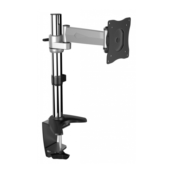
TS5111
Monitor Tischhalterung
Horizontal / Waagerecht
VESA-Befestigungslöcher
Vertikal /
Senkrecht
Bildschirm Rückseite
75mm , 100mm
75mm , 100mm
75x75
100x100
MONTAGEANLEITUNG
v.16.8
ACHTUNG: NIEMALS DAS MAXIMAL
ZULÄSSIGE BELASTUNGSGEWICHT
ÜBERSCHREITEN. MISSACHTUNG
KANN ZU SACHSCHÄDEN ODER
SCHWEREN VERLETZUNGEN FÜHREN!
10kg
(22lbs)
MAX
Deutsch
English
Advertisement

Related Manuals for ricoo TS5111


Summary of Contents for ricoo TS5111
- Page 1 Bitte überprüfen Sie VOR der Montage den Lochabstand zwischen den VESA-Befestigungslöchern an Ihrem Bildschirm! VESA-Befestigungslöcher Vertikal / Senkrecht Horizontal / Waagerecht Bildschirm Rückseite Diese Wandhalterung unterstützt folgende Lochabstände: Horizontal / Waagerecht 75mm , 100mm Vertikal / Senkrecht 75mm , 100mm 10kg TS5111 75x75 (22lbs) 100x100 Deutsch English...
- Page 2 ACHTUNG: Lesen Sie die gesamte Bedienungsanleitung durch, bevor Sie mit der Montage beginnen. WARNUNG • Beginnen Sie nicht mit der Montage, bis Sie alle Anweisungen und Warnungen, welche in dieser Montageanleitung vorhanden sind, durchgelesen und verstanden haben. Wenn Sie Fragen zu den Anweisungen oder Warnungen haben, kontaktieren Sie bitte Ihren Händler.
- Page 3 Lieferumfang WICHTIG: Stellen Sie vor der Montage sicher, dass alle Teile welche hier aufgeführt sind, bei der Lieferung dabei sind. Sollten Teile fehlen oder defekt sein, kontaktieren Sie Ihren Händler. A (x1) B (x1) C (x1) G (x1) 3mm (x1) F (x1) 4mm (x1) H (x1)
- Page 4 Schritt 1 Das Aufkleben des Gummipads ist in der Regel nur bei den Tischen mit Glas-Tischplatten notwendig und dient dem Schutz der Glasoberfläche der Tischplatte. festziehen Höhe einstellen lösen Fixierring festziehen aufkleben* Schritt 2 2a. Montage an die Tischkante Beachten : min. Tischdicke = 10mm max.
- Page 5 2b. Montage im Tischloch ø:10mm~70mm Deutsch English...
- Page 6 Schritt 3 Deutsch English...
- Page 7 Schritt 4 Deutsch English...
- Page 8 Schritt 5 Deutsch English...
- Page 9 Fertg 180° 180° 360° +20° Wartung • Prüfen Sie in regelmäßigen Abständen (mindestens alle drei Monate), ob alle Schrauben an dem Produkt fest angezogen sind. • Bei Fragen kontaktieren Sie Ihren Händler. Deutsch English...
- Page 10 Please check BEFORE installation distance between mounting holes on your display! VESA-Mounting holes Vertical / Perpendicularly Horizintally Display back This wall mount supports the following distance between holes: Horizontally 75mm , 100mm 75mm , 100mm Vertical / Perpendicularly 10kg TS5111 75x75 (22lbs) 100x100 English Deutsch...
- Page 11 NOTE: Read the entire instruction manual before you start installation and assembly. WARNING • Do not begin the installation until you have read and understood all the instructions and warnings contained in this installation sheet. If you have any questions regarding any of the instructions or warnings, please contact your local distributor.
-
Page 12: Component Checklist
Component Checklist IMPORTANT: Ensure that you have received all parts according to the component checklist prior to installation. If any parts are missing or faulty, telephone your local distributor for a replacement. A (x1) B (x1) C (x1) G (x1) 3mm (x1) F (x1) 4mm (x1) - Page 13 Step 1 The adhesive bonding of the rubber pad is normally necessary only if it is a glas-topped table. It serves to protect the glas surface of the tabletop. tighten adjust height Fixing ring loosen tighten stick on* Step 2 2a.
- Page 14 2b. Hole Installation ø:10mm~70mm English Deutsch...
- Page 15 Step 3 English Deutsch...
- Page 16 Step 4 English Deutsch...
- Page 17 Step 5 English Deutsch...
- Page 18 Done 180° 180° 360° +20° Maintenance • Check that the bracket is secure and safe to use at regular intervals(at least every three months). • Please contact your distributor if you have any questions. English Deutsch...
Need help?
Do you have a question about the TS5111 and is the answer not in the manual?
Questions and answers