
Related Manuals for Lucent Technologies Stinger STGR-LIM-AD-48


Summary of Contents for Lucent Technologies Stinger STGR-LIM-AD-48
- Page 1 ® Stinger ADSL 48-Port Annex A Line Interface Module (LIM) Guide For software version 9.2-167 December 2001...
- Page 2 In rare instances, unauthorized individuals make connections to the telecommunications network through the use of access features. Trademarks Lucent, the Lucent logo, and all Lucent brand and product names are trademarks or registered trademarks of Lucent Technologies Inc. Other brand and product names are trademarks of their respective holders.
-
Page 3: Customer Service
Customer Service Product and service information, and software upgrades, are available 24 hours a day. Technical assistance options accommodate varying levels of urgency. Finding information and software To obtain software upgrades, release notes, and addenda for this product, log in to Lucent OnLine Customer Support at http://www.lucent.com/support. -
Page 5: Table Of Contents
Contents Customer Service ........................iii About This Guide ................xi What is in this guide........................xi What you should know ......................xi Documentation conventions...................... xi Stinger documentation set....................... xii Chapter 1 Configuring an ADSL 48-Port Annex A Line Interface Module (LIM) ............1-1 Installing an ADSL 48-port Annex A LIM ................ - Page 6 Contents Checking LIM redundancy status ................... 2-8 Checking status with the Rearslot command ..............2-9 Configuring LIM port redundancy..................2-9 Enabling LIM port redundancy..................2-11 Manual LIM port redundancy..................2-11 Automatic LIM port redundancy .................. 2-12 Checking the status of extended LIM port redundancy ..........2-13 Stinger®...
- Page 7 Figures Figure 1-1 ADSL 48-port Annex A LIM ............... 1-3 Figure 1-2 Relationship between noise margin parameters and power adjustments..1-13 Figure 1-3 Future support: Noise margins and dynamic rate adaptation relationship . 1-15 Figure 1-4 ADSL ATM LIM configuration ..............1-18 Figure 2-1 LIM redundancy in a Stinger FS ..............
- Page 9 Tables Table 1-1 ADSL 48-port Annex A LIM status lights ........... 1-4 Stinger® ADSL 48-Port Annex B LIM Guide...
-
Page 11: About This Guide
About This Guide What is in this guide This guide describes how to configure and monitor the Stinger ADSL 48-port Annex A line interface module (LIM) and includes configuration examples and module specifications. This guide also describes how to configure LIM redundancy. Warning: Before installing your Stinger unit, be sure to read the safety instructions in the Edge Access Safety and Compliance Guide. -
Page 12: Stinger Documentation Set
About This Guide Stinger documentation set Convention Meaning Square brackets indicate an optional argument you might add to a command. To include such an argument, type only the information inside the brackets. Do not type the brackets unless they appear in boldface. - Page 13 About This Guide Stinger documentation set – Module guides. For each Stinger line interface module (LIM), trunk module, or other type of module, an individual guide describes the module's features and provides instructions for configuring the module and verifying its status. •...
-
Page 15: Chapter 1 Configuring An Adsl 48-Port Annex A Line Interface Module (Lim)
Configuring an ADSL 48-Port Annex A Line Interface Module (LIM) Installing an ADSL 48-port Annex A LIM ........1-1 Module specifications . -
Page 16: Interpreting Adsl 48-Port Annex A Status Lights
Configuring an ADSL 48-Port Annex A Line Interface Module (LIM) Interpreting ADSL 48-port Annex A status lights Temperature range FS/LT version: 32°F through 131°F (0°C through 55°C) RT version: -40°F through 149°F (-40°C through 65°C) Interface standards ANSI T1E1.4/99-006 (draft). Network Timing Reference An 8kHz reference clock is provided over the (NTR) -
Page 17: Figure 1-1 Adsl 48-Port Annex A Lim
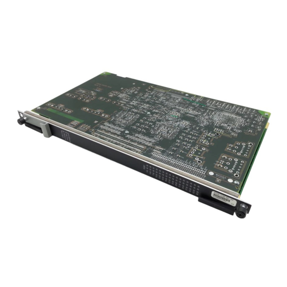
Configuring an ADSL 48-Port Annex A Line Interface Module (LIM) Interpreting ADSL 48-port Annex A status lights Figure 1-1. ADSL 48-port Annex A LIM All status lights illuminate briefly upon startup or restart, then remain dark until the module passes its power-on self test (POST). When the module passes the POST and becomes operational, the ACTIVE light illuminates. -
Page 18: Configuring Atm Adsl-Dmt Interfaces
Configuring an ADSL 48-Port Annex A Line Interface Module (LIM) Configuring ATM ADSL-DMT interfaces Table 1-1. ADSL 48-port Annex A LIM status lights Light Color Indication STBY Orange The module is a designated spare. The control module switches traffic to the module if one of the other modules fails. -
Page 19: Adsl Protocol Support
Configuring an ADSL 48-Port Annex A Line Interface Module (LIM) Configuring ATM ADSL-DMT interfaces • Rate adaptive mode parameters • Power spectral density (PSD) and power-level parameters • Fast and interleaved bit-rate parameters • Interleaving delay parameters • Noise margin parameters •... -
Page 20: Line-Config Subprofile
Configuring an ADSL 48-Port Annex A Line Interface Module (LIM) Configuring ATM ADSL-DMT interfaces enabled = no sparing-mode = inactive Parameter Description name Specifies the name of the interface. The default value is the interface address in shelf : slot : port format (for example, 1:2:3 ), but you can assign a text string of up to 16 characters. - Page 21 Configuring an ADSL 48-Port Annex A Line Interface Module (LIM) Configuring ATM ADSL-DMT interfaces fbm-dbm-mode = fbm alcatel-us-413-boost = unknown Parameter Description nailed-group Specifies the nailed-group number for the ADSL-DMT physical interface. A Connection or RADIUS profile uses this number to specify the interface.
-
Page 22: Rate-Adaptive Mode Parameters
Configuring an ADSL 48-Port Annex A Line Interface Module (LIM) Configuring ATM ADSL-DMT interfaces Parameter Description loop-back Provides a digital or analog loop-back on the ADSL interface when set to digital or analog . No loopback is present when the default setting of none is set. bit-swapping Used as a noise compensation feature on Annex A full-rate lines. -
Page 23: Power-Level Parameters And Power Spectral Density (Psd)
Configuring an ADSL 48-Port Annex A Line Interface Module (LIM) Configuring ATM ADSL-DMT interfaces For details about specifying bit rates, see “Fast and interleaved bit-rate parameters” on page 1-10. For information about defining acceptable noise margins, see “Noise margin parameters” on page 1-13. The following parameters in the Line-Config subprofile, shown with default values, define how rate adaptation operates on the line: [in AL-DMT/{ any-shelf any-slot 0 }:line-config]... -
Page 24: Fast And Interleaved Bit-Rate Parameters
Configuring an ADSL 48-Port Annex A Line Interface Module (LIM) Configuring ATM ADSL-DMT interfaces max-aggr-power-level-down = 20 max-power-spectral-density = 40 gain-default = 16-db Parameter Description max-aggr-power-level-up Specifies the maximum aggregate power level on the upstream channel. Valid range is from 0dBm through 13dBm. -
Page 25: The Interleave-Path-Config Subprofile
Configuring an ADSL 48-Port Annex A Line Interface Module (LIM) Configuring ATM ADSL-DMT interfaces admin> read al-dmt {1 2 1} AL-DMT/{ shelf-1 slot-2 1 } read admin> set fast-path-config max-bitrate-up = 1280 admin> set fast-path-config max-bitrate-down = 12480 admin> set fast-path-config min-bitrate-up = 32 admin>... - Page 26 Configuring an ADSL 48-Port Annex A Line Interface Module (LIM) Configuring ATM ADSL-DMT interfaces Parameter Description Specifies the constant bit rate for upstream traffic when planned-bitrate- operator-controlled rate-adaptive mode is in use. Valid values are from 0Kbps through 2,000Kbps. The default value for the ADSL 48-port Annex A LIM is 512Kbps.
-
Page 27: Margin-Config Subprofile
Configuring an ADSL 48-Port Annex A Line Interface Module (LIM) Configuring ATM ADSL-DMT interfaces Margin-Config subprofile The bit-error rate (BER) is the percentage of erroneous bits in the total number of transmitted bits. The noise margins can be controlled to ensure that the line provides a BER of 10 better, as required by DMT standards. - Page 28 Configuring an ADSL 48-Port Annex A Line Interface Module (LIM) Configuring ATM ADSL-DMT interfaces admin> set max-add-noise-margin-down = 10 admin> set max-margin-enabled = yes You cannot set a value for the parameter to a value that is max-add-noise-margin-down less than that of the target-noise-margin-down parameter. Doing so causes the system to generate the following error message: error: Setting in MARGIN not supported for card.
-
Page 29: Figure 1-3 Future Support: Noise Margins And Dynamic Rate Adaptation Relationship
Configuring an ADSL 48-Port Annex A Line Interface Module (LIM) Configuring ATM ADSL-DMT interfaces Dynamic rate-adaptive noise margin parameters Dynamic rate adaptation is not yet supported. Therefore, if you set any of the parameters described in this section, the modem retrains with its previous behavior. When dynamic rate adaptation is in use, the line adjusts its bit rate dynamically (it upshifts to increase its bit rate or downshifts to reduce it) on the basis of specified noise margins and intervals for which a noise level is maintained, provided that the maximum or minimum bit rate has not been reached. -
Page 30: Configuring Call Control
Configuring an ADSL 48-Port Annex A Line Interface Module (LIM) Configuring call control Parameter Description Not currently supported. Specifies the upstream noise margin ra-upshift-margin- relative to 0dB. If the noise level remains at this value for more than the specified time interval, the line increases its upstream bit rate.The valid range is 1dB through 31dB. - Page 31 Configuring an ADSL 48-Port Annex A Line Interface Module (LIM) Configuring call control Parameter Description In the System profile, enables or disables the Stinger system’s ability ignore-lineup to ignore line status when determining whether calls are established or not. Specify one of the following values: •...
-
Page 32: Examples Of Adsl-Dmt Interface Configuration
Configuring an ADSL 48-Port Annex A Line Interface Module (LIM) Configuring call control Examples of ADSL-DMT interface configuration In Figure 1-4, an ADSL-DMT interface in a Stinger unit is configured to support a rate-adaptive connection to a DSL-CELL-50A CPE. Figure 1-4. ADSL ATM LIM configuration Ethernet DSL-CELL-50A POTS... -
Page 33: Configuring Selective Frequency Bin Loading
Configuring an ADSL 48-Port Annex A Line Interface Module (LIM) Configuring selective frequency bin loading admin> set interleave-path-config max-bitrate-up = 256 admin> set interleave-path-config min-bitrate-down = 512 admin> set interleave-path-config max-bitrate-up = 1500 admin> write AL-DMT/{ shelf-1 slot-3 4 } read The following commands reserve VPI 7 for VP switching on the interface: admin>... -
Page 34: Configuring The Stinger To Disable A Frequency Bin
Configuring an ADSL 48-Port Annex A Line Interface Module (LIM) Checking status of ADSL-DMT interface Configuring the Stinger to disable a frequency bin To determine the frequency bin number to disable for a known frequency, take the frequency and divide it by 4.3125kHz and add 1 to the result. For example, to mask the frequency of an AM radio station at 640kHz, divide 640 by 4.3125. -
Page 35: Checking Status Of The Physical Interface
Configuring an ADSL 48-Port Annex A Line Interface Module (LIM) Checking status of ADSL-DMT interface physical-status = { 0 coe port-up 128 2944 fast fast 1.4.1 2 0 1 init-+ physical-statistic = { { 1 1 1 } yes 3 passed 3 6 56 19 5 41 11 0 0 0 +} Parameter Description Indicates the overall state of the line. - Page 36 Configuring an ADSL 48-Port Annex A Line Interface Module (LIM) Checking status of ADSL-DMT interface down-stream-latency = interleave firmware-ver = 1.4.1 ansi-adsl-ver = 2 initial-adsl-ver = 0 hardware-ver = 1 modem-hw-state = init-ok accum-bit-err = 0 num-sec-valid = 91 num-sec-invalid = 0 operational-mode = g.lite Parameter Description...
-
Page 37: Obtaining Statistics About Operations
Configuring an ADSL 48-Port Annex A Line Interface Module (LIM) Checking status of ADSL-DMT interface Parameter Description Indicates the supported issue of the ANSI T1.413 standard ansi-adsl-ver (Issue 2). Indicates the hardware version of the ADSL modem. hardware-ver Indicates the state of the interface after initialization. Valid modem-hw-State values are init-ok (all is well), bad-sdram , bad-cache , or bad-cache-sdram . -
Page 38: Displaying Adsl-Dmt Port Status And Nailed Groups
Configuring an ADSL 48-Port Annex A Line Interface Module (LIM) Checking status of ADSL-DMT interface incoming-cells = 92 outgoing-cells = 100 Parameter Description Indicates how long the interface has been up (days, hours, and line-up-timer minutes in {dd hh mm} format). rx-signal-present Indicates whether receiving ( yes ) or not receiving ( no ) signal from the CPE. - Page 39 Configuring an ADSL 48-Port Annex A Line Interface Module (LIM) Checking status of ADSL-DMT interface admin> dmtal -a All ADSL lines: (dvOp dvUpSt dvRq sAdm nailg) Line Idle 00151) Line Idle 00152) Line Idle 00153) Line Idle 00154) Line Idle 00155) Line Idle...
-
Page 41: Configuring Lim And Lim Port Redundancy
Configuring LIM and LIM Port Redundancy Overview of LIM and LIM port redundancy ....... . . 2-1 Configuring LIM redundancy . -
Page 42: Overview Of The Lim-Sparing-Config Profile
Configuring LIM and LIM Port Redundancy Configuring LIM redundancy In the same way, a system can be set up with the following module pairs: • 6 SDSL LIM–LPM-RP pairs • 1 SDSL–PSM pair or SDSL–CLT module pair • 6 ADSL LIM–LPM-RP pairs •... - Page 43 Configuring LIM and LIM Port Redundancy Configuring LIM redundancy Following is a listing of a LIM-Sparing-Config profile with all parameters set to their default values: [in LIM-SPARING-CONFIG/{ any-shelf any-slot 0 }] physical-address* = { any-shelf any-slot 0 } spare-slot-type = none sparing-mode = inactive spare-slot-number = slot-16 manually-spared-slot-number = any-slot...
-
Page 44: Manual Lim Redundancy
Configuring LIM and LIM Port Redundancy Configuring LIM redundancy admin> list [in LIM-SPARING-CONFIG/{ shelf-1 slot-14 0 }] physical-address* = { shelf-1 slot-14 0 } spare-slot-type = al-dmtadsl-atm-card sparing-mode = inactive spare-slot-number = slot-14 manually-spared-slot-number = slot-any auto-lim-sparing-config = { [ { yes 10 100 12 } { yes 10 100 12 } { yes 10 100 + Similarly, you can display the profile for the spare SDSL LIM: admin>... - Page 45 Configuring LIM and LIM Port Redundancy Configuring LIM redundancy Monitoring continues on the secondary LIM. If modem errors exceed thresholds, the connections are transferred back to the primary LIM and the automatic redundancy process stops. You can restart the process by resetting the system or by setting the sparing-mode parameter to inactive and then back to automatic.
-
Page 46: Lim Redundancy With Irms And Lpm-Rs
Configuring LIM and LIM Port Redundancy Configuring LIM redundancy To activate automatic LIM redundancy for a particular LIM, you must set the following two parameters: • In the LIM-Sparing-Config profile for the spare LIM, set the following active parameter to yes: Auto-LIM-Sparing-Config > LIM-Sparing-Config [slot number of backed-up LIM] >... - Page 47 Configuring LIM and LIM Port Redundancy Configuring LIM redundancy admin> dir lim-sparing-config 06/20/1999 02:25:18 { shelf-1 slot-16 0 } Then list the profile: admin> read lim-sparing-config { 1 16 0 } admin> list [in LIM-SPARING-CONFIG/{ shelf-1 slot-16 0 } ] physical-address* = { shelf-1 slot-16 0 } spare-slot-type = sdsl-atm-card sparing-mode = inactive...
-
Page 48: Checking Lim Redundancy Status
Configuring LIM and LIM Port Redundancy Configuring LIM redundancy LIM-SPARING-CONFIG/{ shelf-1 slot-16 0 } written LOG notice, Shelf 1, Slot 8, Time: 26:30:01-- LIM 16 ACTIVATED as spare for LIM 4 Checking LIM redundancy status You can check the status of LIM redundancy by examining the LIM-Sparing-Status profile. Following are the parameters with sample values: [in LIM-SPARING-STATUS] spare-slot-type = none... -
Page 49: Checking Status With The Rearslot Command
Configuring LIM and LIM Port Redundancy Configuring LIM port redundancy Parameter Indicates State of the redundancy function. If redundancy is not sparing-state enabled, sparing-none is the value. If redundancy is enabled and the LIM slot is a primary LIM, the value can be primary-active or primary-inactive. -
Page 50: Figure 2-2 Lim Port Redundancy On A Stinger Fs
Configuring LIM and LIM Port Redundancy Configuring LIM port redundancy the spare. The remaining ports on the spare LIM remain available to back up other failed ports on any LIMs of the same type in the system. More than one kind of LIM port can be backed up. An additional LIM-PSM pair (or LIM-CLT module pair) of another type installed in a Stinger can be used to back up other LIMs of that type in the system. -
Page 51: Enabling Lim Port Redundancy
Configuring LIM and LIM Port Redundancy Configuring LIM port redundancy Enabling LIM port redundancy Redundancy for a particular slot and port is controlled by the sparing-mode parameter in the appropriate LIM profile. The sparing-mode parameter appears in all LIM profiles, as in the following SDSL profile for slot 2, port 6: [in SDSL/{ shelf-1 slot-2 6 }] name = 1:2:32... -
Page 52: Automatic Lim Port Redundancy
Configuring LIM and LIM Port Redundancy Configuring LIM port redundancy admin> read sdsl {1 4 6} admin> set sparing-mode = manual admin> write LOG notice, Shelf 1, Slot 8, Time: 12:07:51-- LIM 16 port 6 ACTIVATED as spare for LIM 4 Port 6 Automatic LIM port redundancy Automatic LIM port redundancy detects a LIM port failure and automatically transfers the port connection to the same port on the spare LIM. -
Page 53: Checking The Status Of Extended Lim Port Redundancy
Configuring LIM and LIM Port Redundancy Configuring LIM port redundancy Checking the status of extended LIM port redundancy The line status profile for a particular LIM shows port redundancy status for the selected port, and information about a spare LIM if one exists. The LIM line status profiles have five parameters to indicate the port redundancy status.
Need help?
Do you have a question about the Stinger STGR-LIM-AD-48 and is the answer not in the manual?
Questions and answers