
Related Manuals for Riello RS 50/E


Summary of Contents for Riello RS 50/E
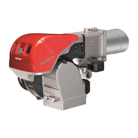
- Page 1 Installation, use and maintenance instructions Forced draught gas burner Progressive two stage or modulating operation Code Model 20053288 RS 50/E 20053677 (3) - 03/2014...
-
Page 3: Table Of Contents
Contents Information and general instructions ..............3 Information about the instruction manual . - Page 4 Contents Flame signal measurement ..............26 Final checks (with the burner working) .
-
Page 5: Information And General Instructions
Information and general instructions Information and general instructions Information about the instruction manual 1.1.1 Introduction 1.1.4 Danger: live components The instruction manual supplied with the burner: This symbol indicates operations which, if not car- is an integral and essential part of the product and must not be ried out correctly, lead to electric shocks with lethal separated from it;... -
Page 6: Guarantee And Responsibility
Information and general instructions Guarantee and responsibility The manufacturer guarantees its new products from the installa- 1.2.1 Owner’s responsibility tion date, in accordance with the regulations in force and/or the Please pay attention to the Safety Warnings contained within sales contract. At the moment of the first start-up, check that the this instruction manual. -
Page 7: Safety And Prevention
Safety and prevention Safety and prevention Introduction The burners have been designed and built in compliance with facturer; current regulations and directives, applying the known technical the type and pressure of the fuel, the voltage and frequency of rules of safety and envisaging all the potential danger situations. the electrical power supply, the minimum and maximum deliv- eries for which the burner has been regulated, the pressurisa- It is necessary, however, to bear in mind that the imprudent and... -
Page 8: Technical Description Of The Burner
Technical description of the burner Technical description of the burner Technical data Model RS 50/E Output High MBtu/hr 1099 - 2201 322 - 645 MBtu/hr Fuel Natural or propane gas – Max delivery SCFH 2201 – Pressure at maximum delivery “... -
Page 9: Burner Models Designation
Technical description of the burner Model RS 50/E Control circuit power supply V/Ph/Hz 120/1/60 Main power supply V/Ph/Hz 575/3/60 3450 W - HP 0.75 Fan motor V1 - V2 120 V - 1 x 8 kV Ignition transformer I1 - I2 1.6 A - 20 mA... -
Page 10: Burner Description
Technical description of the burner Burner description 46 20 35 33 26 Fig. 1 20057349 Combustion head 33 Burner terminal board “X1” Ignition pilot 34 RWF40 modulator (with analog output 4-20 mA) Screw for combustion head adjustment 35 Lifting rings Sleeve 36 Relay “K2”... -
Page 11: Packaging - Weight
Packaging - weight The burners are skid mounted. Outer dimensions of packaging are indicated in Tab. E. The weight of the burner complete with packaging is indicated in Tab. E. inch RS 50/E 32“ 16“ 16“ Tab. E Fig. 2 Burner dimensions The maximum dimensions of the burners are given in (Fig. -
Page 12: Firing Rate
Model MBtu/hr The firing rate area values have been obtained con- RS 50/E sidering an ambient temperature of 68 °F, and an atmospheric pressure of 394” WC and with the WARNING combustion head adjusted as shown at page 19. - Page 13 Technical description of the burner CORRECTED BURNER CAPACITY ACCORDING TO ALTITUDE Altitude m a.s.l. 1220 1525 1830 2135 2440 Rated Capacity ft a.s.l 1000 2000 3000 4000 5000 6000 7000 8000 1000 1000 1023 1061 1101 1142 1186 1232 1282 1337 1500 1481...
-
Page 14: Commercial Boilers
Technical description of the burner Commercial boilers The burner is suitable for operation on either flame-inversion boil- ers or boilers with combustion chambers featuring flow from the base (three flue passes) on which the best results are obtained in 8” max terms of low NOx emissions. -
Page 15: Control Box For The Air/Fuel Ratio (Lmv37.4
Technical description of the burner 3.11 Control box for the air/fuel ratio (LMV37.4...) Warning notes To avoid injury to persons, damage to property or the environment, the following warning notes must be observed! WARNING The LMV37.4... is a safety device! Do not open, interfere with or modify the unit. - Page 16 Technical description of the burner Technical data LMV37.4... basic unit Mains voltage AC 120 V -15 % / +10 % Mains frequency 50 / 60 Hz ±6 % Power consumption < 30 W (typically) Safety class I, with parts according to II and III to DIN EN 60730-1 Terminal loading Unit fuse F1 (internally) 6.3 AT...
- Page 17 Technical description of the burner Operation sequence of the burner Operation Startup Shutdown Valve proving TSA2 TSA1 Phase number Safety limit thermostat (STB) Control thermostat or pressurestat (R) Flame signal (FS) Air pressure switch (LP) Pressure switch-min (Pmin) Pressure switch-max (Pmax) Valve proving / leakage test (P LT) POC (alternative to Pmax) Motor (M)
-
Page 18: Actuators (Sqm33.5
Technical description of the burner 3.12 Actuators (SQM33.5...) Warning notes To avoid injury to persons, damage to property or the environment, the following warning notes should be observed! WARNING Do not open, interfere with or modify the actua- tors! All activities (mounting, installation and service work, etc.) must be performed by qualified staff. -
Page 19: Installation
Boiler plate Drill the combustion chamber mounting plate as shown in Fig. 10. The position of the threaded holes can be marked using the head gasket supplied with the burner. inch RS 50/E 32“ 16“ Tab. G D455 Fig. 10... -
Page 20: Blast Tube Length
The range of lengths available, L (inch), is as follows: Model (short blast tube) (long blast tube) RS 50/E “ “ For boilers with front flue passes 6) or flame inversion cham- bers, protective insulation 4) must be inserted between the boiler refractory 5) and the blast tube 3). -
Page 21: Combustion Head Setting
When the MIN output is within the value range given in Tab. H, the gas ring 2) (Fig. 13) is adjusted to zero. Model MBtu/hr RS 50/E 321 - 488 94 - 143 Tab. H There are two possible cases: The MIN burner output is not in the values of Tab. -
Page 22: To Open The Burner
Installation 4.8.2 To open the burner Switch off the electrical power. WARNING To open the burner proceed sa follows: remove screws 2)(Fig. 16) and withdraw the cover 3); remove the screws 4) from the slide bars 5); install the extention bars 7); ... -
Page 23: Gas Train
p (“ WC) Model MBtu/hr 1099 0.87 0.87 1249 1.14 1402 1.42 1.61 1552 1.69 2.01 RS 50/E 1706 1.97 2.36 1856 2.76 2006 2.48 3.15 2197 2.83 3.78 Tab. I Gas manifold pressure measured at test point 1)(Fig. 19), with: –... -
Page 24: Electrical Wiring
Installation 4.12 Electrical wiring Notes on safety for the electrical wiring The electrical wiring must be carried out with the electrical supply disconnected. Electrical wiring must be carried out by qualified personnel and in compliance with the regulations currently in force in the country of destination. -
Page 25: Thermal Relay Calibration
Installation 4.13 Thermal relay calibration Depending on the burner type, there are two different thermal re- 4.13.2 Electronic thermal relay lays: To reset, in the case of an intervention of the thermal relay, – Electro-mechanical termal relay (used for single phase motors) press the button “RESET”... -
Page 26: Start-Up, Calibration And Operation Of The Burner
Start-up, calibration and operation of the burner Start-up, calibration and operation of the burner Notes on safety for the first start-up The first start-up of the burner must be carried out Check the correct working of the adjustment, com- by qualified personnel, as indicated in this manual mand and safety devices. -
Page 27: Burner Start-Up
Start-up, calibration and operation of the burner Burner start-up Feed electricity to the burner via the disconnecting switch on the For the start-up procedure and the parameters boiler panel. calibration, refer to the specific instruction man- Close the thermostats/pressure switches, set the parameters on ual of the LMV37... -
Page 28: Maximum Gas Pressure Switch (If Installed)
Start-up, calibration and operation of the burner 5.5.2 Maximum gas pressure switch (if installed) Adjust the maximum gas pressure switch (Fig. 30) after having per- formed all other burner adjustments with the maximum gas pres- sure switch set to the end of the scale. With the burner operating at MAX output, reduce the adjustment pressure by slowly turning the adjustment dial anticlockwise until the burner locks out. -
Page 29: Final Checks (With The Burner Working)
Start-up, calibration and operation of the burner Final checks (with the burner working) Open the control limit operation The burner must stop Open the high limit operation Rotate the maximum gas pressure switch knob to the mini- mum end-of-scale position (if installed) The burner must stop in lockout ... -
Page 30: Maintenance
Maintenance Maintenance Notes on safety for the maintenance The periodic maintenance is essential for the good operation, UV scanner safety, yield and duration of the burner. Clean the glass cover from any dust that may have accumulated. It allows you to reduce consumption and polluting emissions and In order to reach the UV scanner, extract the flame sensor to keep the product in a reliable state over time. -
Page 31: Opening The Burner
Maintenance Opening the burner 6.2.1 To open the burner 6.2.2 To close the burner To close the burner proceed as follows: push the burner 13)(Fig. 36) at approximately 4” from the elec- Switch off the electrical power. trical board 14); ... -
Page 32: A Appendix - Spare Parts
Appendix - Spare parts Appendix - Spare parts 20053677... - Page 33 Appendix - Spare parts CODE DESCRIPTION 3003760 3014194 GRADUATE SECTOR 3003830 SOUND DAMPING 20027040 AIR INTAKE 20027422 SWITCH 20031411 RWF40 ASSEMBLY 20010962 BUTTON 20036017 SIGNAL LIGHT 20036019 SIGNAL LIGHT 3003763 INSPECTION WINDOW 20026772 20026773 COVER 3013727 SCREW 20026784 VIEWING PORT 20026787 IGNITION PILOT TUBE 20010968...
- Page 34 Appendix - Spare parts CODE DESCRIPTION 3003396 UV PHOTOCELL 3005483 SEAL 3013004 FLANGE AND ELBOW 3012841 BASE 20014366 FUSE HOLDER 20010969 RELAY 3020071 BASE 3020068 RELAY 3003764 BAR EXTENSION 3003203 PISTON SEAL 20026793 CONNECTOR 3012088 CONNECTOR 20031413 HORN 20030705 CONTACTOR A DVISED PARTS = Spare parts for minimum fittings = Spare parts for basic safety fittings...
-
Page 35: B Appendix - Accessories
Appendix - Accessories • Kit for lengthening the combustion head Standard Length obtainable Burner Code length with kit RS 50/E ” ” 3010258 • Kit for LPG operation The kit allows the burner to operate on LPG. Burner MBtu/hr Code... -
Page 36: Appendix - Burner Start Up Report
Appendix - Burner start up report Appendix - Burner start up report Model number: Serial number: Project name: Start-up date: Installing contractor: Phone number: GAS OPERATION : Low Fire Gas Supply Pressure: High Fire : Low Fire Main Power Supply: High Fire Control Power Supply: CO: Low Fire... - Page 40 RIELLO S.p.A. I-37045 Legnago (VR) Tel.: +39.0442.630111 http:// www.riello.it http:// www.riello.com RIELLO BURNERS NORTH AMERICA 1-800-4-RIELLO 35 Pond Park Road 2165 Meadowpine Blvd Hingham, Massachusetts, 1-800-474-3556 Mississauga, Ontario U.S.A. 02043 Canada L5N 6H6 http://www.riello.ca Subject to modifications...
Need help?
Do you have a question about the RS 50/E and is the answer not in the manual?
Questions and answers