
Related Manuals for Epple Maschinen GB 33

Summary of Contents for Epple Maschinen GB 33
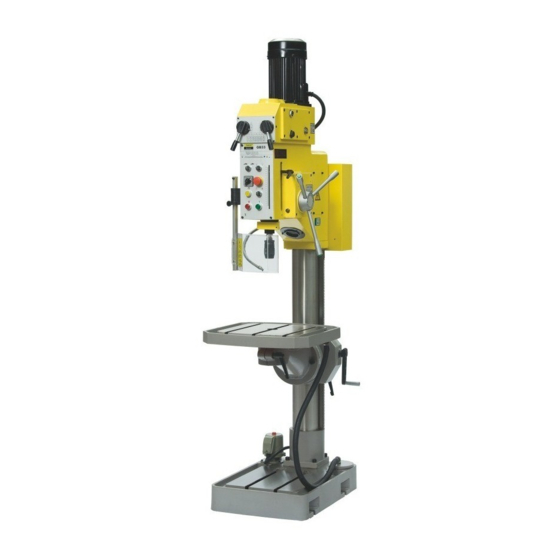
- Page 1 User manual Geared head drill GB 33 Keep for future reference! Stand 02.01.09, GB 33, Geared head drill Page 1 of 52...
-
Page 2: Table Of Contents
Operatin material ....................20 Emissions......................20 ASSEMBLY ...................... 21 Delivery volume ....................21 Transport ......................21 Storage ......................21 Positioning and assembly ................22 3.4.1 Claims to installation location..............22 Stand 02.01.09, GB 33, Geared head drill Page 2 of 52... - Page 3 4.12.2 Fixing the work part in the vice ..............31 MAINTENANCE ....................32 Safety ......................... 32 5.1.1 Preparation ....................32 5.1.2 Recommissioning ..................32 Inspection and attendance ................33 5.2.1 Daily work ....................33 Stand 02.01.09, GB 33, Geared head drill Page 3 of 52...
- Page 4 17.2 Oil change ......................49 18 EG – DECLARATION OF CONFORMITY ............50 19 INSPECTION CERTIFICATE ................51 19.1 Inspection certificate GB 33 ................51 20 ACCEPTANCE CERTIFICATE ................ 52 Stand 02.01.09, GB 33, Geared head drill Page 4 of 52...
- Page 5 Stand 02.01.09, GB 33, Geared head drill Page 5 of 52...
-
Page 6: Safety
If you are unable to solve a problem using this manual, please contact us for advice: Epple Maschinen GmbH Service und Support Auf der Breite 2-14 D-73349 Wiesensteig Stand 02.01.09, GB 33, Geared head drill Page 6 of 52... -
Page 7: Safety Notes (Warning Notes)
No dangerous or harmful consequences for personal or objects. In case of specific dangers, we replace the pictogram by General Injuries to hand Dangerous, danger electrical tension Stand 02.01.09, GB 33, Geared head drill Page 7 of 52... -
Page 8: More, Used Pictograms
If the machine is used in any way other than as described above, modified without authorisation of Epple Maschinen GmbH or operated with different process data, then it is being used improperly. We do not take any liabilities for damage caused by improper use. We would like... -
Page 9: Danger, Which Can Emanate From Drill
It is very important that you disconnect the machine for cleaning and maintenance work. Warning! The machine only can be used with functioning safety equipment. The machine must be disconnected directly if you notice damaged or failure safety equipment. Stand 02.01.09, GB 33, Geared head drill Page 9 of 52... -
Page 10: Qualification Of Personnel
Only authorized personnel may operate the machine. Authorised personnel for the use and maintenance are: Trained and instructed operators Trained and instructed experts of the retaile Stand 02.01.09, GB 33, Geared head drill Page 10 of 52... -
Page 11: The Operator Must
Announce defects directly to your superior Read and understood the user manual To be familiar with all safety regulations and safety arrangements Use the machine Stand 02.01.09, GB 33, Geared head drill Page 11 of 52... -
Page 12: Special Claims To The Qualification
Consequences can be heavy injuries until death. The machine includes the following safety equipment: Main switch lcokable EMERGENCY STOP control Chip protection Stand 02.01.09, GB 33, Geared head drill Page 12 of 52... -
Page 13: Main Switch Lockable
1.6.3 Chip protection Click the chip protection in front of the tool for drilling. If the chip protection is not closed, the drive does not start. Picture 3: Chip protection Stand 02.01.09, GB 33, Geared head drill Page 13 of 52... -
Page 14: Prohibition, Instruction And Warning Signs
EMERGENCY Stop the machine directly after use of the STOP control emergency Stop control. Chip protection Functions during swing out like an emergency Stop control and deactivates the drive. Stand 02.01.09, GB 33, Geared head drill Page 14 of 52... -
Page 15: Personal Protective Equipment For Special Work
CAUTION! Contaminated, defiled protectives can release indispositions. Clear them up after every use and at least once a week. Stand 02.01.09, GB 33, Geared head drill Page 15 of 52... -
Page 16: Safety During The Use Of The Machine
Observe the accident prevention regulations that are effective for your business Announce damages directly to your superior Only leave the machine after deactivating if it stopped completely Stand 02.01.09, GB 33, Geared head drill Page 16 of 52... -
Page 17: Safety During General Maintenance Work
Check before working with lifting tool whether it is admitted for the load and undamaged. Assure that the load is fixed correctly. Never step under lifted loads. Please observe the effective accident prevention regulations for your business. Stand 02.01.09, GB 33, Geared head drill Page 17 of 52... -
Page 18: Mechanic Attendance Work At The Machine
– off the machine in an emergency. The machine must be out off gear immediately by failure in the electrical supply. You will find more information in chapter maintenance. Stand 02.01.09, GB 33, Geared head drill Page 18 of 52... -
Page 19: Technical Data
2.260 mm Weight 470 kg Necessary working room Width 2.000 mm Depth 2.000 mm Height 3.000 mm Environmental conditions 5 – 45°C Temperature range Air humidity Up to max. 75% Stand 02.01.09, GB 33, Geared head drill Page 19 of 52... -
Page 20: Operatin Material
Operatin material To advance the durability of the machine we advise you to accomplish regularly an oil change. Epple Maschinen © advises you to use an oil of the following manufacturers: Feed gear Driving gear Required amount: ca. 0,5 L Required amount: ca. -
Page 21: Assembly
By an improper storage the machine or machine parts can be damaged. Never store the machine under other environmental conditions than in the operation manual denoted. The warranty claim declines by improper storage. Stand 02.01.09, GB 33, Geared head drill Page 21 of 52... -
Page 22: Positioning And Assembly
Observe during position the machine the accident prevention regulations for your business. The use, attendance and maintenance may not be limited. Bethink: A cramped work place retrieves accident risks. Stand 02.01.09, GB 33, Geared head drill Page 22 of 52... -
Page 23: First Initiation
The machine turning field is adjusted at clockwise rotation. Check whether the circuit (coverage of the feed line) is accordant to the information of the machine connection data. Stand 02.01.09, GB 33, Geared head drill Page 23 of 52... -
Page 24: Function Check
3.5.6 Cooling liquid facility Before the first initiation you have to fill up the cooling liquid facility with an adequate coolant. Only use eco – friendly, water soluble coolants. Stand 02.01.09, GB 33, Geared head drill Page 24 of 52... -
Page 25: Handling
You have red, understood and observed the user manual If failures during use encounter you, remove them immediately. Stop the machine directly by a function failure and ensure them against undeliberate or unwarranted resetting. Stand 02.01.09, GB 33, Geared head drill Page 25 of 52... -
Page 26: Control And Indicator Elements
T the control panel are located at: Switch „EMERGENCY STOP“ Switch „drive ON“ – switch „drive OFF“ Turning switch „Table UP/DOWN“ Display for „drive ON“ and „feed ACTIVE“ Depth scale Stand 02.01.09, GB 33, Geared head drill Page 26 of 52... -
Page 27: Overview Control Elements Mechanical
Picture 6: chip protection cover open (left) and close (right) If the chip protection cover is not closed, the drive can not be activated. An opening during the use leads to a machine stoppage. Stand 02.01.09, GB 33, Geared head drill Page 27 of 52... -
Page 28: Activating The Machine
If you push „EMERGENCY STOP“ happens the same, but the complete control of the machine is deactivated. You can disconnect the machine from the grid with the main switch. Stand 02.01.09, GB 33, Geared head drill Page 28 of 52... -
Page 29: Hand Drive/ Function Mode
Now the cutting cycle has finished. Do not make more than 8 threadings per minute so that the overcurrent relay of the main motor does not get too hot. Insert accordant breaks. Stand 02.01.09, GB 33, Geared head drill Page 29 of 52... -
Page 30: Adjust Driving Speed
At the right of the control panel and below you find the depth display. Choice lever for depth arrester at the right side of the housing body. Picture 7: Drilling depth scale GB 33 Stand 02.01.09, GB 33, Geared head drill Page 30 of 52... -
Page 31: Activate Coolant Flow
4.12.2 Fixing the work part in the vice Ascertain that the work part is clamped correct and feast in the vice Shore up overlaying parts with a support block Stand 02.01.09, GB 33, Geared head drill Page 31 of 52... -
Page 32: Maintenance
1.7. Warning! Assure before starting the machine that no danger for body and life exists and the machine possesses no defects. Stand 02.01.09, GB 33, Geared head drill Page 32 of 52... -
Page 33: Inspection And Attendance
Check the feast fit of the anchor screws Check the heald spring motion of the centre sleeve fetching 5.2.5 Yearly work Clean up and refill the gear corresponding to lubrication plan Stand 02.01.09, GB 33, Geared head drill Page 33 of 52... -
Page 34: Maintenance
Adequate and technical blameless tool Only original replacement parts or replacement parts which are freed assertively and in written form by the Epple Maschinen GmbH may be obstructed. Stand 02.01.09, GB 33, Geared head drill Page 34 of 52... -
Page 35: Failures
Switch depth arrester defect Replace end switch The motor shifts too Switch of the depth arrester early during threading Ajdust arrester new adjusted false Stand 02.01.09, GB 33, Geared head drill Page 35 of 52... -
Page 36: Circuit Diagram
7 Circuit diagram Circuit diagram GB 33 Stand 02.01.09, GB 33, Geared head drill Page 36 of 52... -
Page 37: Exploded Drawing
8 Exploded drawing Exploded drawing table, foot Stand 02.01.09, GB 33, Geared head drill Page 37 of 52... -
Page 38: Replacement Part List
Screws M8 x 16 Reducer fitting Bow piece Pipe Pipe Connection piece T-piece Screws M8 x 12 Oiler Gear shaft Table bracket Table Screws M14 x 55 Shim Bearing Stand 02.01.09, GB 33, Geared head drill Page 38 of 52... -
Page 39: Exploded Drawing
10 Exploded drawing 10.1 Exploded drawing gear head 1 Stand 02.01.09, GB 33, Geared head drill Page 39 of 52... -
Page 40: Exploded Drawing Gear Head 2
10.2 Exploded drawing gear head 2 Stand 02.01.09, GB 33, Geared head drill Page 40 of 52... -
Page 41: Replacement Part List
Oil pipe Gear wheel Gasket ring Holding ring Gear housing cover Holding ring beam Gear wheel O-ring Screw M6 x 10 Distance ring Shim Bearing Gear shaft Arbor Holding ring Stand 02.01.09, GB 33, Geared head drill Page 41 of 52... -
Page 42: Exploded Drawing
12 Exploded drawing 12.1 Exploded drawing feed Stand 02.01.09, GB 33, Geared head drill Page 42 of 52... -
Page 43: Replacement Part List
M24 x 1,5 Plate Screws M4 x 6 Gasket ring Screws M5 x 8 Holding angle Acceptor Screws M8 x 40 Grip Hand wheel Cover Bolt Screws M6 x 12 Plate Stand 02.01.09, GB 33, Geared head drill Page 43 of 52... -
Page 44: Exploded Drawing
14 Exploded drawing 14.1 Exploded drawing drilling head 1 Stand 02.01.09, GB 33, Geared head drill Page 44 of 52... -
Page 45: Exploded Drawing Drilling Head 2
14.2 Exploded drawing drilling head 2 Stand 02.01.09, GB 33, Geared head drill Page 45 of 52... -
Page 46: Replacement Part List
Ring Screw M6 x 12 Bolt Spring Screws M8 x 45 Clamping bush Bolt Bracket Screw M8 x 8 Axis Plate Cover plate Plate Screws M6 x 8 Shim Stand 02.01.09, GB 33, Geared head drill Page 46 of 52... -
Page 47: Appendix
Serial – No. Date of purchase Ca. running time per day Epple Maschinen GmbH Auf der Breite 2-14 73349 Wiesensteig Fax: 07335 9243 300 E-Mail: info@epple.com Stand 02.01.09, GB 33, Geared head drill Page 47 of 52... -
Page 48: Technichal Appendix
¼ yearly grease the gear head Gear rack column Table adjustment monthly Spindle monthly Lubrication with oil Feed gear ½ yearly Feed lever ¼ yearly Driving speed switch ¼ yearly Stand 02.01.09, GB 33, Geared head drill Page 48 of 52... -
Page 49: Oil Change
The fill - up capacity is 0,4 kg gear oil, that is ca. 0,5 litre. Driving gear Feed gear To advance the durability of the gear we advise a regular oil change. Epple Maschinen © advises you oil from the following manufacturers: Feed gear Driving gear Required amount: ca. 0,5 L Required amount: ca. -
Page 50: Eg - Declaration Of Conformity
The manufacturer Epple Maschinen GmbH Auf der Breite 2-14 73349 Wiesensteig Declares herewith, that the machine of the type GB 33 agrees with the claims of the following norms: Safety of tool machines – drilling machines EN12717:2001 And works accordant to the following guide lines:... -
Page 51: Inspection Certificate
19 Inspection certificate 19.1 Inspection certificate GB 33 Stand 02.01.09, GB 33, Geared head drill Page 51 of 52... -
Page 52: Acceptance Certificate
Illuminating checked: Emergency stop switch/ control checked: Earth conductor test accomplished Mechanic corresponding to examine statement note Mechanical operating parts checked: Show window oil checked: Date of acceptance Signature examiner Stand 02.01.09, GB 33, Geared head drill Page 52 of 52...
Need help?
Do you have a question about the GB 33 and is the answer not in the manual?
Questions and answers