Table of Contents
Advertisement
Quick Links
Advertisement
Table of Contents

Related Manuals for Vintage Air 564191


Summary of Contents for Vintage Air 564191
-
Page 1: Cover
ISO 9001:2015 Registered Company 1969 Chevrolet Camaro with Factory Air Evaporator Kit (564191) 18865 Goll St. San Antonio, TX 78266 Phone: 800-862-6658 Sales: sales@vintageair.com Tech Support: tech@vintageair.com www.vintageair.com 905644 REV A 01/10/19, PG 1 OF 33... -
Page 2: Table Of Contents
Troubleshooting Guide......................31-32 Packing List........................A detailed tech video outlining the installation process is available on Vintage Air’s YouTube channel at http://bit.ly/2GWAxWY. Viewing the tech video along with the written instructions will provide the installer the most detailed installation procedure. -
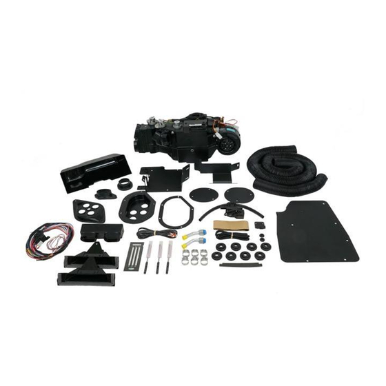
Page 3: Packing List/Parts Disclaimer
Accessory Kit ** Before beginning installation, open all packages and check contents of shipment. Please report any shortages directly to Vintage Air within 15 days. After 15 days, Vintage Air will not be responsible for missing or damaged items. Gen IV Evaporator... -
Page 4: Information Page, Wiring Notice
Refrigerant Capacities: Vintage Air System: 1.8 lbs. (28.8 oz.) or 816 grams of R134a, charged by weight with a quality charging station or scale. NOTE: Use of the proper type and amount of refrigerant is critical to system operation and performance. - Page 5 Vintage Air strives to harden our products against these types of electrical noise, but there is a point where a vehicle’s electrical system can be degraded so much that nothing can help.
-
Page 6: Brackets
To avoid damage to the paint and sheet metal, and for ease of removal and replacement of components, Vintage Air recommends that the right fender be removed, and the inner panel lowered. Removing the right front tire will provide easier access to the inner fender bolts. -
Page 7: Center Louver Modification
Center Louver Modification www.vintageair.com Remove the center louver assembly from the dash (See Figure 1, below). Locate the flange seal foam and the 1” foam piece (See Photos 1 & 2, below). Install the flange seal foam onto the center louver assembly as shown in Photo 3, below. Install the 1”... -
Page 8: Passenger Compartment Disassembly
Passenger Compartment Disassembly www.vintageair.com NOTE: Removal of the dashboard is required to install the evaporator. Vintage Air recommends using the factory manual when disassembling and reassembling the dashboard. Perform the Following: Remove the glove box door (retain) (See Figure 4, below). -
Page 9: Firewall Modification, Defrost Duct & Fresh Air Cover Installation
Firewall Modification www.vintageair.com NOTE: Firewall modification is required for firewall cover and drain hose installation. Flatten the edges of the firewall opening (See Photo 1, below). Enlarge (6) holes on the firewall to 19/64” as shown in Photo 2, below. From inside the passenger compartment, directly below the lowest OEM hole under the firewall opening, mark and drill a 5/8”... -
Page 10: Hose Adapter Installation, Early-Model Kick Panel Modification
Hose Adapter Installation www.vintageair.com Cut off 9” of the OEM driver side A/C duct assembly as shown in Figure 1, below. Install (3) S-clips onto each hose adapter as shown in Figure 1, below. Install the driver & passenger side hose adapters onto the OEM louvers (See Figure 1, below). Reinstall the louvers into the dash. -
Page 11: Late-Model Kick Panel Modification
Late-Model Kick Panel Modification www.vintageair.com Remove the fresh air door assembly from the OEM kick panel by lifting up on the door toward the spring and sliding it out of the hinge housing (See Photo 1, below). Disconnect and remove the fresh air door cable from the OEM lever housing (discard) (See Photo 2, below). Trim the fresh air door housing flush with the back of the OEM kick panel, and discard the excess material (See Photo 3, below). -
Page 12: Firewall Cover Insulation
Firewall Cover Insulation www.vintageair.com NOTE: For proper system operation, Vintage Air recommends using heat blocking insulation in the area around the evaporator unit (firewall, kick panel, inner cowl, firewall covers). Due to tight clearance for the evaporator unit between the firewall and dash, Vintage Air recommends an insulation thickness of no more than 1/4”. -
Page 13: Lubricating O-Rings, Evaporator Bracket & Heater Hardline Installation
Lubricating O-rings www.vintageair.com For a proper seal of fittings: Install supplied Male Female Nut O-rings as shown, and lubricate with supplied O-ring Insert oil. #6 O-ring O-ring Figure ## Supplied Oil O-ring Installs for O-rings Over Male Insert #10 O-ring #8 O-ring to Swaged Lip Twist With... -
Page 14: Fresh Air Cap & Kick Panel Cover Preparation, Heater And A/C Hose Installation
Fresh Air Cap & Kick Panel Cover Preparation www.vintageair.com Install (4) large grommets and a 7/8” grommet into the fresh air cap (See Photos 1 and 2, below). Install (4) large grommets and a 7/8” grommet into the kick panel cover (See Photos 3 and 4, below). 7/8”... - Page 15 Heater and A/C Hose Installation (Cont.) www.vintageair.com Insert a length of heater hose through the bottom right large grommet on the fresh air cap (See Photo 2, below). Insert a length of heater hose through the top right large grommet on the fresh air cap (See Photo 3, below). Insert the straight fitting on the #6 drier/evaporator A/C hose through the bottom left large grommet on the fresh air cap (See Photo 4, below).
-
Page 16: Wiring Installation, Kick Panel Installation
Wiring Installation www.vintageair.com From the passenger compartment, route the heater control valve connector and wiring (red, white and green) through the 7/8” grommet in the kick panel cover and through the 7/8” grommet in the fresh air cap (See Photo 1, below). NOTE: Leave approximately 1” of wiring between the kick panel cover and the harness connector. - Page 17 Kick Panel Installation www.vintageair.com Apply a bead of silicone around the mating surface of the kick panel cover (See Figure 1, below). Install the kick panel cover into place, lining up the mounting holes on the cover with the OEM mounting holes on the kick panel opening (See Photo 1, below).
-
Page 18: Evaporator Installation, Drain Hose Installation
Evaporator Installation www.vintageair.com NOTE: A 10” block of wood may be used to support the evaporator unit while the following steps are completed. Place the evaporator unit under the dash (See Photo 1, below). Install the straight fitting on the #6 drier/evaporator A/C hose onto the expansion valve on the evaporator unit using a properly lubricated #6 O-ring (See Figure 1, Page 13, and Photo 2, below). - Page 19 Evaporator Installation (Cont.) www.vintageair.com Locate the evaporator dash bracket (See Photo 8, below). Install the (2) #8 U-nuts onto the bracket as shown in Photo 8, below. Install the dash bracket onto the evaporator unit using (2) 1/4-20 x 1/2” bolts (supplied on the evaporator unit). NOTE: Do not fully tighten the bolts at this time.
-
Page 20: Firewall Cover Installation
NOTE: To ensure a watertight seal between the passenger compartment and the exterior, for all bolts passing through the firewall, Vintage Air recommends coating the threads with silicone prior to installation. Locate the bottom left mounting hole on the firewall cover, and install a 1/4-20 x 3/4” bolt and a 1/4”... -
Page 21: Ecu Wiring Harness Installation
ECU Wiring Harness Installation www.vintageair.com Route the violet power wire to a switched 12v power source on the fuse panel (See Photo 1, below). NOTE: This requires a male fuse extension (not supplied) (See Photo 2, below). Plug the white connector from the heater control valve into the white connector on the main wiring harness (See Photo 3, below). -
Page 22: Duct Hose Installation
Duct Hose Installation www.vintageair.com Passenger Side Louver 2 ½” x 43” Passenger Side Center Louver 2 ½” x 25” Driver Side Center Louver 2 ½” x 25” Passenger Side Center Louver Passenger Side Defrost Duct 2” x 12” Driver Side Defrost Duct 2”... -
Page 23: Fresh Air Cap Installation, A/C Hose Installation
Fresh Air Cap Installation www.vintageair.com Reinstall the large grommet on the #10 compressor/evaporator A/C hose into the fresh air cap (See Photo 1, below). Gently pull the slack from the hoses in the passenger compartment, making sure the hoses are not kinked. Slide the fresh air cap into position, and secure it to the firewall using (2) #14 x 3/4”... -
Page 24: Heater Control Valve Installation
Heater Control Valve Installation www.vintageair.com NOTE: Vintage Air Systems use 5/8” heater connections. On engines equipped with 3/4” hose nipples, these will need to be removed and replaced with 5/8” nipples (not supplied). For water pumps with a cast-in 3/4” heater outlet, a 3/4” x 5/8” reducer fitting in the heater hose (not supplied) or molded hose (Vintage Air Part #099010) will need to be installed. -
Page 25: Wiring Final Steps
Wiring Final Steps www.vintageair.com Reconnect the circuit breaker, and mount it as close as possible to battery (See Photo 1, below). Route the blue lead from the main wiring harness to the safety switch (See Photo 2, below). Connect the compressor lead wire to the safety switch (See Photo 2, below). Wrap the safety switch wiring with flexo sleeve, and secure it with the supplied tie wraps (See Photo 3, below). -
Page 26: Center Louver Installation, Glove Box Installation
Center Louver Installation www.vintageair.com Attach (2) 25” lengths of 2 ½” duct hose to the center louver as shown in Figure 1, below. Install the center louver assembly into the dash, and secure it with the OEM mounting screws as shown in Figure 2, below. -
Page 27: Final Steps, Wiring Diagram
Double check all fittings, brackets and belts for tightness. Vintage Air recommends that all A/C systems be serviced by a licensed automotive A/C technician. Evacuate the system for a minimum of 45 minutes prior to charging, and perform a leak check prior to servicing. - Page 28 Wiring Diagram www.vintageair.com 232007-VUR AC ANNUNCIATOR BACKLIGHT POS BACKLIGHT NEG 5V-SW WHT/RED TEMP WIPER WHT/YEL MODE WIPER WHT/GRN FAN WIPER PRE-WIRED VIEWED FROM WIRE SIDE GEN IV ECU 232002-VUA GEN IV WIRING DIAGRAM (IF USED) REV E, 10/6/2017 TEMP MODE PROGRAM * DASH LAMP (IF USED)
-
Page 29: Gen Iv Wiring Connection Instruction
HARNESS TERMINAL) HARNESS ARE NOT IGNITION USED. Dash Light: YELLOW SWITCH ORANGE Tan Wire Used Only With Vintage Air Supplied Control Panel With LED Back DASH BACK LIGHT+0-12v Light. GRAY GRAY WIRE IS USED FOR PROGRAMING CONTROLS IF APPLICABLE GREEN... -
Page 30: Operation Of Controls
Operation of Controls www.vintageair.com On Gen IV systems with three lever/knob controls, the temperature control toggles between heat and A/C operations. To activate A/C, move the temperature lever/knob all the way to cold and then back it off to the desired vent temperature. -
Page 31: Troubleshooting Guide
905644 REV A 01/10/19, PG 31 OF 33... - Page 32 905644 REV A 01/10/19, PG 32 OF 33...
-
Page 34: Packing List
Packing List: Evaporator Kit (564191) www.vintageair.com Qty. Part No. Description 744004-VUE Gen IV Evaporator Sub Case 784191 Accessory Kit Checked By: Packed By: Date: Gen IV Evaporator Sub Case 744004-VUE O F F H O T C O L D...
Need help?
Do you have a question about the 564191 and is the answer not in the manual?
Questions and answers