Table of Contents
Advertisement
Quick Links
Advertisement
Table of Contents

Related Manuals for Asus Pro Q470M-C


Summary of Contents for Asus Pro Q470M-C
- Page 1 Pro Q470M-C...
- Page 2 Product warranty or service will not be extended if: (1) the product is repaired, modified or altered, unless such repair, modification of alteration is authorized in writing by ASUS; or (2) the serial number of the product is defaced or missing.
-
Page 3: Table Of Contents
Contents Safety information ...................... iv About this guide ......................v Package contents ....................... vi Pro Q470M-C specifications summary ..............vi Connectors with shared bandwidth ................. ix Chapter 1 Product introduction Before you proceed ..................1-1 Motherboard overview ................. 1-1 Central Processing Unit (CPU) ..............1-8 System memory .................... -
Page 4: Safety Information
Safety information Electrical safety • To prevent electrical shock hazard, disconnect the power cable from the electrical outlet before relocating the system. • When adding or removing devices to or from the system, ensure that the power cables for the devices are unplugged before the signal cables are connected. If possible, disconnect all power cables from the existing system before you add a device. -
Page 5: About This Guide
Refer to the following sources for additional information and for Product and software updates. ASUS website The ASUS website Provides updated information on ASUS hardware and software Products. Refer to the ASUS contact information. Optional documentation Your Product package may include optional documentation, such as warranty flyers, that may have been added by your dealer. -
Page 6: Package Contents
Processors, only Core™ i9/i7 CPUs support ® 2933/2800/2666/2400/2133 natively, others will run at the maximum transfer rate of DDR4 2666MHz. ** Refer to www.asus.com for the Memory QVL (Qualified Vendors Lists). 2 x DisplayPorts 1.4** 1 x D-Sub 1 x HDMI 1.4b... - Page 7 Pro Q470M-C specifications summary M.2_2 slot (Key M), type 2242/2260/2280 (supports PCIe 3.0 x4 mode) 6 x SATA 6Gb/s ports Intel Rapid Storage Technology supports Raid 0,1,5,10 ® Storage Intel Optane™ Memory Ready ® * When a device in SATA mode is installed on the M.2_1 socket, SATA6G_2 port cannot be used.
- Page 8 Pro Q470M-C specifications summary Miscellaneous 1 x Clear CMOS header 1 x Chassis Intrude header 2 x COM Port headers 1 x Front Panel Audio header (AAFP) 1 x Intel ME Jumper ® Internal I/O 1 x LPC Debug header...
-
Page 9: Connectors With Shared Bandwidth
Connectors with shared bandwidth KBMS CPU_FAN EATX12V DIGI +VRM DP_12 LGA1200 U32G2_12 U32G2_34 CHA_FAN1 LAN_USB56 Intel ® M.2_1(SOCKET3) I219LM PCIE SATA IRST AUDIO 2280 2260 2242 22110 PCIEX16 Super 2230 Intel ® Q470 1083 M.2_2(SOCKET3) PCIEX1 PCIE SATA IRST MONO_OUT 128Mb BIOS 2280... -
Page 11: Chapter 1 Product Introduction
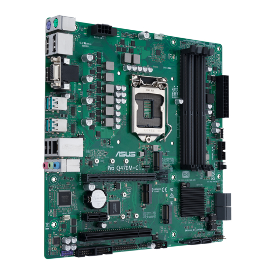
1083 M.2_2(SOCKET3) PCIEX1 PCIE SATA IRST MONO_OUT 128Mb BIOS 2280 2260 2242 64Mb BIOS CLRTC COM2 COM1 USB1112 SATA6G_6 SATA6G_5 LPC_DEBUG CHASSIS AAFP F_PANEL DIS_ME SPEAKER 10 6 Unplug the power cord before installing or removing the motherboard. Failure to do so can cause you physical injury and damage motherboard components. ASUS Pro Q470M-C... - Page 12 1.2.1 Layout contents 1. CPU socket The motherboard comes with a surface mount Intel Socket LGA1200 designed for 10 ® Intel Core , Pentium Gold and Celeron Processors. ® ® ® For more details, refer to Central Processing Unit (CPU). 2. DDR4 DIMM slots The motherboard comes with Dual Inline Memory Modules (DIMM) slots designed for DDR4 (Double Data Rate 4) memory modules.
- Page 13 11. Clear CMOS header This header allows you to clear the CMOS RTC RAM data of the system setup information such as date, time, and system passwords. To erase the RTC RAM: Turn OFF the computer and unplug the power cord. CLRTC 2. Use a metal object such as a screwdriver to short the two pins. 3. Plug the power cord and turn ON the computer. Hold down the <Del> key during the boot process and enter BIOS PIN 1 setup to re-enter data. If the steps above do not help, remove the onboard battery and short the two pins again to clear the CMOS RTC RAM data. After clearing the CMOS, reinstall the battery. ASUS Pro Q470M-C...
- Page 14 AAFP • If you want to connect a high-definition front panel audio module to this header, set the Front Panel Type item in the BIOS setup to [HD Audio]. By default, this header is set to [HD Audio]. HD-audio-compliant pin definition 16. LPC Debug header This header allows connection to a LPC Debug card. LPC_DEBUG • Scan the QR code to view the meaning of each debugging code. • Debugging codes are only available for ASUS LPC Debug cards. PIN 1 • Contact your region sales representative for LPC Debug cards ordering. 17. LPT header The LPT (Line Printing Terminal) header supports devices such as a printer. LPT standardizes as IEEE 1284, which is the parallel port interface on IBM PC-compatible computers. PIN 1 Chapter 1: Product introduction...
- Page 15 HDD. • Power button/Soft-off button (2-pin PWR_BTN) This header is for the system power button. • Reset button (2-pin RESET) This 2-pin header is for the chassis-mounted reset button for system reboot without turning off the system power. ASUS Pro Q470M-C...
- Page 16 1.2.2 Rear panel connectors PS/2 Mouse port (green). This port is for a PS/2 mouse. Video Graphics Adapter (VGA) port. This 15-pin port is for a VGA monitor or other VGA-compatible devices. USB 3.2 Gen 2 (up to 10Gbps) ports. These 9-pin Universal Serial Bus (USB) ports are for USB 3.2 Gen 2 devices. Ethernet port. This port allows Gigabit connection to a Local Area Network (LAN) through a network hub. Refer to the table below for the Ethernet port LED indications. Ethernet port LED indications Speed Activity Link Activity/Link LED Speed LED Status Description Status Description No link...
- Page 17 Rear Speaker Out Rear Speaker Out Rear Speaker Out (Rear panel) Lime (Rear panel) Line Out Front Speaker Out Front Speaker Out Front Speaker Out Pink (Rear panel) Mic In Mic In Bass/Center Bass/Center Lime (Front panel) — — — Side Speaker Out To configure a 7.1-channel audio output: Use a chassis with HD audio module in the front panel to support a 7.1-channel audio output. ASUS Pro Q470M-C...
-
Page 18: Central Processing Unit (Cpu)
Gen Intel Core™, Pentium Gold and Celeron ® ® ® Processors. Unplug all power cables before installing the CPU. • Ensure that you install the correct CPU designed for the LGA1200 socket only. DO NOT install a CPU designed for LGA1150, LGA1151, LGA1155 and LGA1156 sockets on the LGA1200 socket. • Upon purchase of the motherboard, ensure that the PnP cap is on the socket and the socket contacts are not bent. Contact your retailer immediately if the PnP cap is missing, or if you see any damage to the PnP cap/socket contacts/motherboard components. • Keep the cap after installing the motherboard. ASUS will process Return Merchandise Authorization (RMA) requests only if the motherboard comes with the cap on the LGA1200 socket. • The product warranty does not cover damage to the socket contacts resulting from incorrect CPU installation/removal, or misplacement/loss/incorrect removal of the PnP cap. Installing the CPU Apply the Thermal Interface Material to the CPU heatsink and CPU before you install the heatsink and fan if necessary. Chapter 1: Product introduction... -
Page 19: System Memory
You may install varying memory sizes in Channel A and Channel B. The system maps the total size of the lower-sized channel for the dual-channel configuration. Any excess memory from the higher-sized channel is then mapped for single-channel operation. • Always install DIMMs with the same CAS latency. For optimal compatibility, we recommend that you install memory modules of the same version or date code (D/C) from the same vendor. Check with the retailer to get the correct memory modules. • For 10 Gen Intel processors, only Core™ i9/i7 CPUs support ® 2933/2800/2666/2400/2133 natively, others will run at the maximum transfer rate of DDR4 2666MHz. • The default memory operation frequency is dependent on its Serial Presence Detect (SPD), which is the standard way of accessing information from a memory module. Under the default state, some memory modules for overclocking may operate at a lower frequency than the vendor-marked value. • For system stability, use a more efficient memory cooling system to support a full memory load (4 DIMMs). • Refer to www.asus.com for the latest Memory QVL (Qualified Vendors List). Recommended memory configurations DIMM_B1 DIMM_B2* DIMM_B2* DIMM_A1 DIMM_A2* DIMM_A2* DIMM_A2* ASUS Pro Q470M-C... - Page 20 Installing a DIMM To remove a DIMM 1-10 Chapter 1: Product introduction...
-
Page 21: Chapter 2 Bios Information
BIOS information ASUS Self-Recovering BIOS ASUS-exclusive BIOS protection technology automatically recovers the system’s BIOS with a verified backup in the event of an update failure, preventing the need to replace or reinstall your hardware. • Ensures safe BIOS updates •... -
Page 22: Bios Menu Screen
The BIOS setup screens shown in this section are for reference purposes only, and may not exactly match what you see on your screen. • Visit the ASUS website at www.asus.com to download the latest BIOS file for this motherboard. •... -
Page 23: Event Log
CPU Over Heating Error! events** CPU Over Voltage Error! * Record of when USB Over Current occurs ** Record of when CPU temperature rises above 75°C ***Record of when CPU Voltage reaches below 0 mV or above 1550mV ASUS Pro Q470M-C... -
Page 24: Exit Menu
Exit menu The Exit menu items allow you to load the optimal default values for the BIOS items, and save or discard your changes to the BIOS items. Aptio Setup Utility - Copyright (C) 2020 American Megatrends, Inc. Main Ai Tweaker Advanced Monitor Boot... -
Page 25: Appendix
Appendix Notices FCC Compliance Information Responsible Party: Asus Computer International Address: 48720 Kato Rd., Fremont, CA 94538, USA Phone / Fax No: (510)739-3777 / (510)608-4555 This device complies with part 15 of the FCC Rules. Operation is subject to the following two conditions: (1) This device may not cause harmful interference, and (2) this device must accept any interference received, including interference that may cause undesired operation. - Page 26 Compliance Statement of Innovation, Science and Economic Development Canada (ISED) This device complies with Innovation, Science and Economic Development Canada licence exempt RSS standard(s). Operation is subject to the following two conditions: (1) this device may not cause interference, and (2) this device must accept any interference, including interference that may cause undesired operation of the device.
- Page 27 ASUS products sold in Vietnam, on or after September 23, 2011,meet the requirements of the Vietnam Circular 30/2011/TT-BCT. Các sản phẩm ASUS bán tại Việt Nam, vào ngày 23 tháng 9 năm2011 trở về sau, đều phải đáp ứng các yêu cầu của Thông tư 30/2011/TT-BCT của Việt Nam.
- Page 28 ASUS Recycling/Takeback Services ASUS recycling and takeback programs come from our commitment to the highest standards for protecting our environment. We believe in providing solutions for you to be able to responsibly recycle our products, batteries, other components as well as the packaging materials.
- Page 29 Директив. Повний текст декларації відповідності стандартам ЄС доступний s bitnim zahtjevima i ostalim odgovarajućim odredbama vezanih direktiva. на: www.asus.com/support Cijeli tekst EU izjave o sukladnosti dostupan je na: www.asus.com/support Türkçe AsusTek Computer Inc., bu aygıtın temel gereksinimlerle ve ilişkili Čeština Společnost ASUSTeK Computer Inc. tímto prohlašuje, že Yönergelerin diğer ilgili koşullarıyla uyumlu olduğunu beyan eder.
-
Page 30: Asus Contact Information
+1-510-739-3777 +1-510-608-4555 Web site https://www.asus.com/us/ Technical Support Support fax +1-812-284-0883 Telephone +1-812-282-2787 Online support https://qr.asus.com/techserv ASUS COMPUTER GmbH (Germany and Austria) Address Harkortstrasse 21-23, 40880 Ratingen, Germany Web site https://www.asus.com/de Online contact https://www.asus.com/support/Product/ContactUs/ Services/questionform/?lang=de-de Technical Support Telephone (DE) +49-2102-5789557 Telephone (AT)
Need help?
Do you have a question about the Pro Q470M-C and is the answer not in the manual?
Questions and answers