
Subscribe to Our Youtube Channel
Related Manuals for Biocare iM 12


Summary of Contents for Biocare iM 12
- Page 1 User Manual Veterinary Monitor Model: iM 12&iM 15 Shenzhen Biocare Bio-Medical Equipment Co., Ltd. P/N: 02111717-01...
- Page 3 For reasons of technical updating and customers‘ special requirements, if the product performance is unaffected, some assembled units may not be in accordance with the standard configurations indicated in the manual. Version: V2.1 Date: 2018-12 All rights reserved © Shenzhen Biocare Bio-Medical Equipment Co., Ltd.
- Page 4 Shanghai International Holding Corp. GmbH (Europe) Eiffestraß e 80 20537 Hamburg GERMANY Shenzhen Biocare Bio-Medical Equipment Co., Ltd. #16-1, Jinhui Road, Jinsha Community, Kengzi Sub-District, Pingshan New District, 518122 Shenzhen, PEOPLE'S REPUBLIC OF CHINA Tel: 86-755-33005899 Fax: 86-755-27960643 Website: http://www.biocare.com.cn...
-
Page 5: Table Of Contents
Content Content Preface ..................................1 Customer Required Reading ..........................3 Chapter 1 Operation Safety Information ......................5 1.1 Safety Information ............................5 1.2 Influence On the Environment and Energy Sources ..................7 1.3 Safety Classification............................7 1.4 Safety Requirements ............................7 1.5 Device Identifications ............................. - Page 6 Content 3.9.4 Time and Date Setup ..........................28 3.9.5 Audio Setup ............................29 3.9.6 Help Menu ............................. 29 3.10 Configuration Management ........................29 3.10.1 Recent Configuration Self-recovery ....................29 3.10.2 Turning-on Default Configuration Setup ..................... 29 3.10.3 User Configuration Storage ......................... 30 3.10.4 User Configuration Deletion........................
- Page 7 Content 6.3 PR .................................. 58 6.3.1 PR General Description ......................... 58 6.3.2 PR Source .............................. 59 6.3.3 Alarm Source Setup ..........................59 6.3.4 Pulse Volume Setup..........................59 6.4 SpO ................................59 6.4.1 SpO General Description ........................59 6.4.2 Safety Information ..........................61 6.4.3 SpO Module ............................
- Page 8 Content 6.8.9 Emissions ............................... 88 6.9 C.O. (Optional) ............................. 89 6.9.1 General Description ..........................89 6.9.2 Influencing Factors of Measurement ..................... 89 6.9.3 Setting Up the C.O. Measurement ......................90 6.9.4 Understanding the C.O. Display ......................92 6.9.5 Changing C.O. Settings ......................... 92 6.9.6 Measuring the Blood Temperature ......................
- Page 9 Content 8.4.5 NIBP List ............................. 119 8.4.6 Long ECG ............................120 Chapter 9 Calculations ............................123 9.1 General Description ............................ 123 9.2 Medication Calculation ..........................123 9.3 Hemodynamic Calculation .......................... 125 9.3.1 Review ..............................125 9.3.2 Output ..............................126 9.4 Renal Function Calculation, Oxygenation Calculation, Ventilation Calculation ........126 Chapter 10 Recording ............................
- Page 10 Content 14.6 Demo Model ............................. 141 14.7 Monitor System Information ........................141 Chapter 15 Troubleshooting and Solutions ....................... 143 15.1 Check before Use ............................143 15.2 The Monitor cannot be Turned On ......................143 15.3 The Monitor cannot be Shut Down Normally with ON/OFF Switch............143 15.4 No Display on Screen ..........................
- Page 11 Content D.3.2 10~20kg ............................171 D.3.3 <10 kg ..............................172 D.4 Screen Setup ............................... 173 D.5 User Maintain ............................. 173 D.6 ECG ................................173 D.7 NIBP ................................175 D.8 SpO ................................175 D.9 Resp ................................176 D.10 IBP ................................176 D.11 CO ................................
- Page 12 Content -- The Blank Page -- --VIII-- User Manual of Veterinary Monitor...
-
Page 13: Preface
For any error and omission in the manual, your notification is welcomed. This series of monitors contain iM 12 (Named as 12 inches monitor in the following) and iM 15 (Named as 15 inches monitor in the following). - Page 14 Preface -- The Blank Page -- --2-- User Manual of Veterinary Monitor...
-
Page 15: Customer Required Reading
Customer Required Reading Customer Required Reading This section will tell you what operative procedures should be paid close attention to, how to avoid abnormal operation, and what possible detrimental risks might occur to this series of monitors or animal when you use this series of monitors. - Page 16 Customer Required Reading pulse count. Do not rely solely on heart rate alarm. Should be closely monitoring animals with pacemaker. Do not modify this series of equipments without authorization of the manufacturer. If this series of equipments are modified, appropriate inspection and testing must be conducted to ensure continued safe use of the equipment.
-
Page 17: Chapter 1 Operation Safety Information
Chapter 1 Operation Safety Information Chapter 1 Operation Safety Information 1.1 Safety Information Warning: emergencies may be caused which may lead to death, severe bodily injuries or property loss if you do not follow this advice. Explanation: instructions or explanations are provided for better use of this series of product. Attention: important information and prompts are included, which may lead to slight bodily injuries or breakdowns of the product if you do not follow them. - Page 18 Chapter 1 Operation Safety Information In order to prevent burns, a high frequency electrosurgical should be kept far away from the electrodes. The electrical resistance between the electrosurgical and the animal‟s body should be as small as possible and great caution should be used. ...
-
Page 19: Influence On The Environment And Energy Sources
Chapter 1 Operation Safety Information minimized the possibility of the risks caused by programming errors. The user manual introduces the product according to its most complete configurations. Therefore, your purchased product may lack some configurations or corresponding functions. 1.2 Influence On the Environment and Energy Sources Handling of the packing materials, exhausted battery and scrap materials should be carried out according to local regulations. - Page 20 Chapter 1 Operation Safety Information Attention: the alarm function of monitoring devices should be checked regularly. Before Use All connection cables should be carefully checked before use. Any damaged cable or connector should be replaced immediately. Cable The cables should be kept away from the animal‘s neck in case of entanglement. ...
-
Page 21: Device Identifications
Chapter 1 Operation Safety Information 1.5 Device Identifications Safety Associated Identification Type CF applied part, defibrillation-proof protection against electric shock, represents that type CF applied parts have a higher protection against electric shock (especially on permissive leakage current) compared to type BF applied parts. Type BF applied part, defibrillation-proof protection against electric shock, represents that type BF applied parts have a higher protection against electric shock (especially on permissive leakage current) compared to type B applied parts. - Page 22 Chapter 1 Operation Safety Information -- The Blank Page -- --10-- User Manual of Veterinary Monitor...
-
Page 23: Chapter 2 Overview
Chapter 2 Overview Chapter 2 Overview 2.1 Brief Introduction 2.1.1 Applicability This series of monitors can be used in monitoring or measuring the electrocardiogram (ECG), non-invasive blood pressure (NIBP), body temperature (Temp), respiration (Resp), EtCO (optional), invasive blood pressure (IBP) (optional), cardiac output (C.O.)(optional) and Anesthetic gas module (AG) (optional) for a single vet. -
Page 24: Main Unit
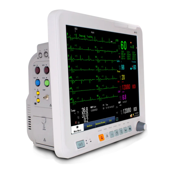
(Art, PA, LAP, RAP, ICP, CVP and P1/P2, optional), end expiration CO (EtCO )/airway respiratory rate (awRR) (optional) and Anesthetic gas (CO [AG], N O, AA, ) (optional). 2.3 Main Unit 2.3.1 Front View Figure 2.1 Front View of iM 12 --12-- User Manual of Veterinary Monitor... - Page 25 Chapter 2 Overview Figure 2.2 Front View of iM 15 1. Physiological Alarm Indicator Lamp Red with a high flicker frequency: a high-level alarm. Yellow with a low flicker frequency: a middle-level alarm. Constantly yellow without flicker: a low-level alarm. ...
- Page 26 Chapter 2 Overview Battery or Battery Charging Indicator Lamp (Only for 15 inches monitor) Battery is charged: Lights flickers; The charge is finished: Lights steadily; Power is supplied by the battery: Light is on (The monitor is on). ...
-
Page 27: Side View
Chapter 2 Overview 2.3.2 Side View Figure 2.3 Left Side View of 12 Inches Monitor Figure 2.4 Left Side View of 15 Inches Monitor User Manual of Veterinary Monitor --15--... - Page 28 Chapter 2 Overview Figure 2.5 Right Side View of 12 Inches Monitor Figure 2.6 Right Side View of 15 Inches Monitor For the convenience of operation, different interfaces are placed on different sections of the monitor. The cable and probe insertion points are placed on the left side of the monitor, as shown in Figure 2.3 (12 inches monitor) /2.4 (15 inches monitor).
-
Page 29: Back View
Chapter 2 Overview 2.3.3 Back View Figure 2.7 Back View of 12 Inches Monitor Figure 2.8 Back View of 15 Inches Monitor The back faceplate contains the following insertions (as shown in Figure 2.7 (12 inches monitor) /2.8 (15 inches monitor) ): A standard RJ45 interface through which the monitor and a central —Network interface... -
Page 30: Screen Display
Chapter 2 Overview 2.5 Screen Display 2.5.1 Main Interface This series of monitors use a colorful high-resolution TFT liquid crystal display screen, which can show the animal‘s physical parameters and waveform information. Figure 2.9 shows its standard interface under a normal monitoring condition. - Page 31 Chapter 2 Overview Technical Alarm Region Technical alarms and prompt information are shown in this region. When there are several pieces of information, they will be displayed in a cycle. When this region is selected, the menu of [Technical Alarm View] can be opened for checking information.
- Page 32 Chapter 2 Overview Figure 2.13 Non-Invasive Blood Pressure Data Region NIBP: blood pressure type identification. Manual: NIBP measure mode. 120/80/93: values of measured NIBP contractive, diastolic and mean blood pressures. 160/90: the upper and lower limits of an NIBP alarm. ...
- Page 33 Chapter 2 Overview Figure 2.16 Anesthetic Gas Data Area MAC: minimum alveolar concentration. 5.0/19.2/45/1.3/(0.3/1.6/21.2/50): CO O and AA end-tidal (Et) and respiratory (Fi) values. Prompt Information Region The prompt information, network state icon, power supply state icon, and date and time are displayed in this region.
-
Page 34: Shortcut Key
Chapter 2 Overview 2.6 Shortcut Key The following shortcut keys are defaulted on the screen: Main Menu Admit Animal Alarm Setup Audio Setup User can customize the shortcut keys. Select [Main Menu] – [System] – [Screen Setup] – [Screen Config], as shown in Figure 2. 17: Figure 2.17 Screen Setup Select [Shortcut Key>>]. -
Page 35: Chapter 3 Basic Operation
Chapter 3 Basic Operation Chapter 3 Basic Operation 3.1 Installation Warning When this series of monitors are connected with other electric equipment for specific functional combinations, if safety cannot be assured based on their separate specifications, please contact the manufacturer or specialized experts in the hospital to secure that the necessary safety of any equipment in the combination won‟t be damaged. -
Page 36: Operation Preparation
Chapter 3 Basic Operation Operating humidity: 15%~80%, non-refrigerated. 3. Atmospheric pressure: 442.5 mmHg~805.5 mmHg (59 kPa~107.4 kPa). Power source: AC 100 V~240 V, 50 Hz/60 Hz, frequency allowance ± 1Hz; DC 14.8 V, 4.4 Ah. Attention Transfer of the monitor from one environment into another may lead to condensation due to a temperature difference. -
Page 37: Sensor Connection
Chapter 3 Basic Operation Attention If the monitor displays evidence of damage or an error prompt, stop using the monitor for Veterinary Monitoring. Please contact the vendor or the company. The interval between restarts should be more than 1 minute. Or, abnormal operation may be caused. -
Page 38: Input Board
Chapter 3 Basic Operation 3.5 Input Board This series of monitors provide a input board for information input such as animal data. Figure 3.1 Input Board [English]: Chinese-English switching. [Backspace]: the preceding character delete. [Caps]: uppercase and lowercase letter switching. [Clr]: a clear key. - Page 39 Chapter 3 Basic Operation In the standard interface layout window, the user can allocate positions to different parameters and waveforms. Those parameters and waveforms without allocated positions won‘t be displayed on the standard interface. Figure 3.3 Standard Screen Layout Setup Functions with displayed waveforms and their corresponding waveforms can be set up in Region 1.
-
Page 40: Main Menu
Chapter 3 Basic Operation 3.8 Main Menu Select the Main Menu Shortcut key on the screen, or press the Main Menu pushbutton on the monitor to open the main menu, as shown in Figure 3.4: Figure 3.4 Main Menu Most operations and setup of the monitor can be accomplished by operating in this menu. 3.9 General Setup 3.9.1 Monitor Definition Select [Main Menu] –... -
Page 41: Audio Setup
Chapter 3 Basic Operation Attention Alterations in date and time may lead to animal data and events data lost. 3.9.5 Audio Setup Alarm Volume Select the [Audio Setup] Shortcut key, or [Main Menu] – [Alarm Setup] – [Global] to set [Alarm volume]: X –... -
Page 42: User Configuration Storage
Chapter 3 Basic Operation Select [Main Menu] – [Maintenance] – [User Maintain>>], input the user maintain password, and then select [Defaults Manage>>] – [Select] to set up the valid time for recent configuration recovery and turning-on default configuration, as shown in Figure 3.5: Figure 3.5 Defaults Manage Attention ... -
Page 43: Default Configuration Manual Restore
Chapter 3 Basic Operation 3.10.5 Default Configuration Manual Restore Restore some default configurations according to the following procedures: Select [Main Menu] – [Defaults], select the company configuration or user configuration according to the animal type, select [Resume], and then select [OK] after the window is displayed to restore the selected default configuration model. - Page 44 Chapter 3 Basic Operation -- The Blank Page -- --32-- User Manual of Veterinary Monitor...
-
Page 45: Chapter 4 Animal Management
Chapter 4 Animal Management Chapter 4 Animal Management 4.1 Admit Animal Select [Main Menu] – [Animal Manage] – [Admit Animal]. If the monitor displays a warning screen, press [Yes] to continue. Input and select all information into the menu [Animal Demographics]. Select [OK] to complete the animal information input. -
Page 46: Data Management
Chapter 4 Animal Management Select [Standby] – [OK], the monitor will carry out animal removal operation, and then enter a standby mode. Exit the standby mode by pressing any key. Select [Cancel], the monitor may exit from the animal removal operation, and then return to the main screen. -
Page 47: Chapter 5 User Interface
Chapter 5 User Interface Chapter 5 User Interface 5.1 Interface Style Setup The user can set up the interface style according to need, including waveform tracing methods, parameter color, monitor parameter setup, screen setup, interface layout, etc. Waveform Tracing Methods Select [Main Menu] –... -
Page 48: Minitrends Interface
Chapter 5 User Interface The user can select the needed parameter labels according to need in the [Std. Screen] menu. 5.3 Minitrends Interface Select [Screen Setup] – [Screen Config] – [Interface Type] – [Minitrends]. The short trend is displayed on the left of the waveform region, and shows the trend of the parameter in the recent time period, as shown in Figure 5.2: Figure 5.2 Minitrends Interface In each minitrends, the parameter label is shown at the top, the scale is shown on the left, and the timescale is... -
Page 49: Bignumerics Interface
Chapter 5 User Interface 5.4 BigNumerics Interface Select [Screen Setup] – [Screen Config] – [Interface Type] – [BigNumerics ]. The big numerics interface is shown in Figure 5.4: Figure 5.4 BigNumerics Interface 5.5 OxyCRG Interface Select [Screen Setup] – [Screen Config] – [Interface Type] – [OxyCRG], which is shown in Figure 5.5: Figure 5.5 OxyCRG Interface In this interface, you may select the time range and RR Trend /Resp Wave gram of the respiratory oxygenation gram, as shown in Figure 5.6:... -
Page 50: View Other Bed Interface
Chapter 5 User Interface Figure 5.6 OxyCRG Setup Trend time length: [1 min], [2 min], [4 min], or [8 min]. Resp Wave/RR Trend: the Resp wave or RR trend can be displayed. Record: the current respiratory oxygenation gram can be printed through a recorder. 5.6 View Other Bed Interface Select [Screen Setup] –... - Page 51 Chapter 5 User Interface Figure 5.8 Other Bed Setup Window View Other Bed Window Figure 5.9 View Other Bed Window When the View Other Bed window is opened for the first time, the monitor will select other bed monitors automatically for observation.
-
Page 52: Measure Screen (Optional)
Chapter 5 User Interface Attention When a parameter in the parameter region has no waveform display, the item Waveform Region Switching will not be available in Parameter Region Selection. Warning As the data display in the other bed observation window has some time delay, don‟t depend on this window to acquire real-time data. -
Page 53: Lead Half Screen
Chapter 5 User Interface 5.8 7 Lead Half Screen Select [Screen Setup] – [Screen Config] – [Interface Type] – [7 Lead Half], as shown in Figure 5.12: Figure 5.12 7 Lead Half Interface 5.9 7 Lead Full Screen Select [Screen Setup] – [Screen Config] – [Interface Type] – [7 Lead Full], as shown in 5.13: Figure 5.13 7 Lead Full Interface User Manual of Veterinary Monitor --41--... - Page 54 Chapter 5 User Interface -- The Blank Page -- --42-- User Manual of Veterinary Monitor...
-
Page 55: Chapter 6 Parameter Monitoring
Chapter 6 Parameter Monitoring Chapter 6 Parameter Monitoring 6.1 ECG 6.1.1 ECG Measuring Principle Brief Description of ECG The heart has its own special electrical conduction system. It is situated within heart walls and consists of specially differentiated myocardial cells. The function is generating and conducting excitations, and maintaining and governing normal heart rhythms. -
Page 56: Definition Of Ecg Monitoring
Chapter 6 Parameter Monitoring Testing Method This series of monitor measure ECG waveform and data by body surface potential mapping method. Body surface potential measure is recorded by placing several electrodes on chest and back, and simultaneously record ECG waveforms from each electrode site at each sampling moment. Since over 200 electrodes are used to measure the body surface potentials, this method can provide the cardio electric potentials of a great many sites on the body surface, which allows a full view of the cardio electric field on the entire body surface and the profile of the electrical cardiac activities for the whole cardiac cycle... -
Page 57: Monitoring Procedures
Chapter 6 Parameter Monitoring Non-defibrillation ECG cables are prohibited for use when defibrillation is needed for animals. During defibrillation, contact with animals, desks or instruments is NOT allowed. Interference caused by ungrounded instruments around the animal and ESU interference may result in distorted waveforms. - Page 58 Chapter 6 Parameter Monitoring Table 6.1 Comparison for the Color of Electrodes and Cable Lead European Standard U.S. Standard Electrode Position Cable Colour Marking Electrode Colour Marking Electrode Colour Right Arm Gray White Left Arm Gray Yellow Black Right Foot Gray N or RF Black...
-
Page 59: Ecg Display
Chapter 6 Parameter Monitoring Electrodes are strictly prohibited from being placed close to the electrosurgical equipment grounding plate when electrosurgical equipment is in use. Otherwise, ECG signals will be severely affected. Check on Pacemaking Status Prior to ECG monitoring, it is important to correctly set animal‘s pacemaking status. When [Paced] is [Yes], ︱... - Page 60 Chapter 6 Parameter Monitoring Figure 6.8 ECG Setup Filter Mode Setup Open the menu [ECG Setup] and select [Filter]: Diagnose: for diagnostic quality requirements. Monitor: for normal measure. Surgery: for occasions where signals are interfered with. Select surgery mode to reduce interference from electrosurgical equipment and other sources.
-
Page 61: St Analysis
Chapter 6 Parameter Monitoring Other Setup Select [ECG Setup]-[Others>>]: QRS Volume: 0-10.0 and 10 indicate mute and the maximum volume, respectively. Notch Filter: when the Filter Mode is ‗Monitor‘ or ‗Surgery‘, the notch filter is defaulted open (50Hz or 60Hz);... -
Page 62: Arrhythmia Monitoring
Chapter 6 Parameter Monitoring ST Display Figure 6.9 shows 5-Lead ST display. Figure 6.9 ST Data Display Select ST parameter region, and enter ST Analysis menu. ST Value A maximum of 12 ST numerical values can be simultaneously displayed on this series of monitors screen. ... -
Page 63: Arrhythmia Alarm
Chapter 6 Parameter Monitoring Warning The arrhythmia analysis function is not suitable for <10 kg. The arrhythmia analysis function is applicable to detection of ventricular arrhythmia, but not for atrial or supraventricular arrhythmia. However, this may lead to detection of incorrect arrhythmia information;... - Page 64 Chapter 6 Parameter Monitoring and Ventricular HR is greater than V-Tach HR Limit. VB (Ventricular Consecutive PVCs are greater than or equal to the vent Bradycardia) rhythm limit and Ventricular HR is lower than the V-Brad HR Limit. Extreme-Tachy Heart rate exceeds extreme tachycardia threshold. Extreme-Brady Heart rate lower than extreme bradycardia threshold.
- Page 65 Chapter 6 Parameter Monitoring Attention Fatal arrhythmia defined in this series of monitors include: Asystole, and VFib/VTac (ventricular fibrillation/ ventricular tachycardia). Please set the fatal arrhythmia alarm switch in [User Maintain>>]-[Alarm Config>>]-[Fatal Arrh.Off]; when [Fatal Arrh.Off] is enabled, the fatal arrhythmia function is stopped, and when disabled, it can‟t be stopped.
- Page 66 Chapter 6 Parameter Monitoring Arrhythmia Alarm Link Red Arrhythmia Alarm Asystole VFib/VTac VTac Ventricular bradycardia Extreme-Tachy Extreme-Brady Yellow Arrhythmia Alarm Heart Beat Detection Alarm Link PVC Alarm Link Heart Rate Alarm Link HeartBeat Pause Non-Sustained VT Tachycardia Bradycardia Run PVCs>2 Missed Beats Couplet PVCs **R on T...
-
Page 67: Ecg Relearn
Chapter 6 Parameter Monitoring For example, when ‗R on T‘ alarms, the ‗V-Trigeminy‘ on the same link will not alarm even if it takes place; if ‗Extreme-Tachy‘ alarm is triggered, ‗R on T‘ will be replaced due to its lower priority even if they belong to two different links. -
Page 68: Resp
Chapter 6 Parameter Monitoring Incorrect heart rate ECG relearn function enables the monitor to learn new ECG templates for correcting arrhythmia alarm and recovering ST measurement. To manually start ECG relearn: select [Main Menu]-[Parameters]-[ECG Setup]-[Relearn], or select ECG Waveform Region or Parameter Region, then [ECG Setup]-[Relearn]. Attention ... -
Page 69: Placing Respiration Electrodes
Chapter 6 Parameter Monitoring 6.2.3 Placing Respiration Electrodes Before placing, you need to treat an animal‘s skin where the electrodes are to be placed, as referred to in skin treating method in the ECG section. The electrodes are connected by referring to above methods mentioned in ECG connection. -
Page 70: Pr General Description
Chapter 6 Parameter Monitoring Resp Lead Setup Select [Resp Lead]: I and II. It allows selecting the desired lead to meet different clinical demands for optimal respiratory waves. Attention In order to obtain optimal respiratory waves, RA and LA electrodes should be kept level when I-lead is selected for resp measure, and RA and LL electrodes should be diagonally kept when II-lead is selected. -
Page 71: Pr Source
Chapter 6 Parameter Monitoring 6.3.2 PR Source Pulse is displayed in PR parameter region. Figure 6.19 PR Parameter Region When effective pulse origin is displayed in the PR parameter region, the pulse rate (PR) of the pulse can be: Detected as the system pulse and an alarm triggered when users select PR as an alarm source. - Page 72 Chapter 6 Parameter Monitoring fractional saturation functional saturation = ( ) %Carboxyhe moglobin %methemogl obin Figure 6.20 SpO Sensor Socket This series of monitors are able to display the functional degree of blood oxygen saturation by displaying on the screen the plethysmography waveform and parameter values, as shown in Figure 6.21: Figure 6.21 SpO Waveform and Parameter Display (SpO...
-
Page 73: Safety Information
Chapter 6 Parameter Monitoring 6.4.2 Safety Information Warning Only the blood oxygen sensor specified in the User manual is allowed; and it should be used by following all warnings and warnings specified in the User manual. If Masimo SpO module or Nellcor SpO module is configured, please carefully read the instructions for the corresponding sensor before use. -
Page 74: Spo Module
Chapter 6 Parameter Monitoring oximeter monitor. However, it can be used to demonstrate a particular calibration curve reproduced by pulse oximeter, and has been proved to meet the specific accuracy specification. If the pulse oximeter has a specific calibration curve and it is accurate for the combination of the pulse oximeter and pulse oximeter probe, the functional tester will be able to measure the overall error of the monitor / probe system from the monitor, and will also be able to test the accuracy of the pulse oximeter that copies the calibration curve. -
Page 75: Spo 2 Setup
Chapter 6 Parameter Monitoring Connection of Pulse Oximetry Probe The pulse oximetry probe is a complex measuring instrument which should be used for measuring by following current methods and steps. Improper operational method may cause damages to the probe. Steps of Operations: Connect the plug of the pulse oximetry probe to the corresponding ‗SpO ‘... - Page 76 Chapter 6 Parameter Monitoring Figure 6.27 SpO Setup (Nellcor SpO Module) NIBP Simul Setup Select [NIBP Simul]: On/Off. It should be set [On] when NIBP and SpO measures are conducted on the same limb of the animal until the NIBP measure is completed so as to maintain SpO physiological alarm state constant while doing NIBP measure.
-
Page 77: Influencing Factors Of Measure
Chapter 6 Parameter Monitoring Satseconds Apply to Nellcor SpO module; to prevent the SpO values exceeding the alarm limit instantly or within a short time and causing false alarms; when the Satseconds function is enabled, the greater the value, the longer the fault-tolerant time is. -
Page 78: Nibp
Chapter 6 Parameter Monitoring 7, 190, 985; 7, 194, 293; 7, 209, 774; 7, 212, 847; 7, 400, 919. No implied license Possession or purchase of this device neither means that you can replace one or some parts of the device, nor means that you can use the patents of the device. -
Page 79: Safety Information
Chapter 6 Parameter Monitoring Comparison of Oscillation Method and Coriolis Sound Method Despite sound correlation of the blood pressure measure between the oscillation method and Coriolis sound method and the invasive blood pressure measuring method, it is one-sided to compare any non-invasive and invasive blood pressure measuring methods;... - Page 80 Chapter 6 Parameter Monitoring shouldn‘t be more than 40 kPa (300 mmHg) for cuffs for >20 kg and 20 kPa (150 mmHg) for <10 kg. Before measuring, the residual air should be evacuated from the cuff. The part where symbol φ is printed on the cuff should be placed where the arterial pulse is most evident on the brachial artery for the best result.
-
Page 81: Measure Restriction
Chapter 6 Parameter Monitoring 6.5.3 Measure Restriction Measure may be inaccurate or cannot be conducted in the following conditions: Blood vessels have severe convulsion, vasoconstriction and excessively weak pulse. The measure is unreliable or inefficient when animals have extremely low or high heart rate or irregular arrhythmia, particularly atrial fibrillation. -
Page 82: Nibp Display
Chapter 6 Parameter Monitoring Attention Cuff width should be appropriate for blood pressure measure, too narrow a cuff will give relatively higher blood pressure values, and too wide gives too low values. The cuff should be completely deflated before use to prevent any inaccurate measure caused by residual air. -
Page 83: Nibp Setup
Chapter 6 Parameter Monitoring Mean pressure NIBP unit 6.5.7 NIBP Setup Select [Main Menu]-[Parameters]-[NIBP Setup] or select NIBP parameter region to open the window [NIBP Setup]. Figure 6.31 NIBP Setup Initial Pressure Setup Select cuff initial pressure values tailored for subjects. ... -
Page 84: Nibp Leakage Test
Chapter 6 Parameter Monitoring Warning Please regularly check the color, warmth and sensitivity of the animal‟s distal limbs in the process of measuring blood pressure under Auto and STAT modes. Once any abnormality is found, please relocate the cuff or terminate blood pressure measure. ... -
Page 85: Nibp Accuracy Test
Chapter 6 Parameter Monitoring No prompting message displayed in the NIBP parameter region indicates that the system is not leaking. Prompting message ‗GasWay Leak!‘ displayed in the NIBP parameter region indicates that the system is possibly leaking. Then operator should further check whether a loosened connection exists and re-conduct the leakage detection when a good connection is confirmed. -
Page 86: Temp
Chapter 6 Parameter Monitoring Figure 6.33 NIBP Calibration Diagram Attention Press either the button [NIBP] on the front panel or [Stop NIBP Accuracy Test], or [Stop All.] and [Stop NIBP] on the interface [NIBP Setup] during accuracy test to terminate accuracy testing. Warning ... -
Page 87: Safety Information
Chapter 6 Parameter Monitoring 6.6.2 Safety Information Explanation When body temperature exceeds the measuring range, alarm is displayed on the screen. Please check if the body temperature sensor is on the animal‟s body correctly and shift it to the proper positions if needed. -
Page 88: Measure Display
Chapter 6 Parameter Monitoring 6.6.4 Measure Display This series of monitors can display T1, T2 and TD (their difference) through two body temperature channels (T1 and T2). Figure 6.35 Temp Data Display 6.6.5 Temp Unit Setup Select [Main Menu]-[Maintenance]-[User Maintain>>], input passwords and select [Units Setup>>]-[Temp], the temperature unit can be: ℃... -
Page 89: Safety Information
Chapter 6 Parameter Monitoring 6.7.2 Safety Information Warning Pressure sensors specified in this User manual only are allowed to be used and repeated use of disposable pressure sensors is not allowed. Contact of the monitor‟s sensors and cables with high-frequency surgical equipment should be avoided in order to prevent animals from being burnt by leaked current when the monitor is in contact with high-frequency surgical equipment. -
Page 90: Ibp Display
Chapter 6 Parameter Monitoring Warning Please flush the system again with solution if any bubbles are found in the conduit system to avert any possible incorrect pressure readings caused by such bubble. The sensors should be leveled with the ears of a sitting animal while measuring his/her intracranial pressure. -
Page 91: Sensor Zero-Calibration
Chapter 6 Parameter Monitoring Filter Setup Select [Filter], and users can choose: Normal and Smooth. Sensitivity Setup The blood pressure values displayed on the monitor are resulting by averaging data sampled within a given period of time. A shorter averaged time represents higher response speed of the monitor yet lower measuring accuracy when the animal‘s blood pressure values are changing. - Page 92 Chapter 6 Parameter Monitoring absorbed energy is directly related to the CO concentration. When the infrared rays emitted from an infrared source penetrate through a CO -containing gaseous sample, part of their energy will be absorbed by the CO in the gaseous sample.
-
Page 93: Side-Stream Co 2 Module
Chapter 6 Parameter Monitoring Warning The CO module can be operated only by authorized or well-trained staff and the operator is required to be familiar with the User manual before using this module. Don‟t use this CO module where anesthetic and other combustible gases are present in the environment to avoid any danger of explosion. - Page 94 Chapter 6 Parameter Monitoring module‟s service life will occur. Excessive negative or positive pressure in the animal‟s tube may affect sampling flow rate. Please insert the sampling tube before connecting a T-valve in the respiratory loop. Please remove the T-valve from the respiratory loop before removing the sampling tube.
-
Page 95: Main-Stream Co 2 Module
Chapter 6 Parameter Monitoring It‟s better not to connect a water tank and set the CO module in stand-by mode when the CO module is not in use to prolong the service life of the water tank and module. ... - Page 96 Chapter 6 Parameter Monitoring sensor. sensor between the ET tube and the elbow (<10~20 kg or >20 Do not place the combined CO kg circuit), as this may allow animal secretions to block the adapter windows. Position the combined CO sensor with its windows in a vertical and not a horizontal position: this helps keep animal secretions from pooling on the windows.
-
Page 97: Co Setup
Chapter 6 Parameter Monitoring Figure 6.46 Attach Airway Adapter to Airway Circuit Ensure the airway air-proof and ready to measure. 6.8.4 CO Setup Open CO Menu Users can open the [CO Setup] through the following three means: Select CO Parameter Region to open [CO Setup]. -
Page 98: Zero
Chapter 6 Parameter Monitoring By taking KM7002-V33 Kingst side-stream module as example: Compen] O Compen] [Des Compen] Operate Mode Select [Operate Mode]: Measure and Standby. In the standby mode, the sampling pump is automatically closed and the measure mode is automatically open, but users can manually close the pump in this mode and resetting the pump speed will forcibly open the closed pump. -
Page 99: Calibrate
Chapter 6 Parameter Monitoring Main-stream The main-stream CO module need zero calibration in the following cases: The airway adapter is exchanged. The sensors is re-connected with the module. The gas readings are found having errors. The system prompts ‗CO Need Zero‘. -
Page 100: Influencing Factors Of Measure
Chapter 6 Parameter Monitoring Figure 6.48 Calibration Diagram Open and regulate throttle valve switch until the flow indicated by the flowmeter is 10ml/min-50ml/min and maintains stable. Select a concentration equal to that of the introduced gases in the menu [CO Maintenance]. -
Page 101: Optional)
Chapter 6 Parameter Monitoring Warning Anesthetic: the sidestream CO module, to measure the use of anesthetics or recently used anesthetic animals, the vent on the module must be connected to the exhaust gas treatment system, anesthesia machine or ventilator, to avoid medical personnel inhalation anesthetic. 6.9 C.O. -
Page 102: Setting Up The C.o. Measurement
Chapter 6 Parameter Monitoring 6.9.3 Setting Up the C.O. Measurement Warning Use only accessories specified in this manual. Make sure that the accessories never come into contact with conductive parts. Attention The temperature of injectable solution must be lower than that of the animal‟s blood. ... - Page 103 Chapter 6 Parameter Monitoring [Comp. Const]: Make sure that the correct computation constant is entered. When a new catheter is used, the computation constant should be adjusted in accordance with the manufacturer‘s instructions for use. [Auto TI]: When [Auto TI] is enabled, the injectate temperature is automatically obtained. ...
-
Page 104: Understanding The C.o. Display
Chapter 6 Parameter Monitoring [Stop]: Select [Stop] to stop the current measurement if the measurement is too long. [Cancel]: During the current measurement, select [Cancel] to cancel the measurement output and stop the current measurement. After a measurement, select [Cancel] to delete the measured output. [Record]: Select [Record] to print out the most recently-measured output. -
Page 105: Measuring The Blood Temperature
Chapter 6 Parameter Monitoring 6.9.6 Measuring the Blood Temperature The blood temperature is measured by a temperature sensor at the distal end of the catheter in the pulmonary artery. During C.O. measurements, blood temperature alarms are inactive to avoid false alarms during measurements and will become active automatically as soon as the C.O. -
Page 106: Mac Value
Chapter 6 Parameter Monitoring Figure 6.50 AG Display AG module can display all measured waveforms and parameters on the monitor screen, such as: O and AA1 waveform. awRR: airway respiration rate. MAC: minimum alveolar concentration. O and AA1: end-tidal (Et) and respiratory (Fi) values. Where, AA1 represents one anesthetic gas of Des (desflurane), Iso (isoflurane), Enf (enflurane), Sev (sevoflurane) and Hal (halothane). - Page 107 Chapter 6 Parameter Monitoring combination with other vital signs monitoring devices and/or professional human judgments of animal condition. The IRMA probe is intended to be used by trained and authorized health care professionals only. System Assembly Instruction Setup Plug the IRMA connector into the IRMA input of <host device> and switch the power on. Snap the IRMA probe on top of a new IRMA airway adapter.
- Page 108 Chapter 6 Parameter Monitoring Connect the IRMA/airway adapter 15 mm female connector to the animal‘s endotracheal tube. Figure 6.54 Alternatively, connect an HME (Heat Moisture Exchanger) between the animal‘s endotracheal tube and the IRMA probe. Placing an HME in front of the IRMA probe protects the airway adapter from secretions and effects of water vapor and eliminates the need of changing the adapter.
- Page 109 Chapter 6 Parameter Monitoring Pre-use Check Prior to connecting the IRMA airway adapter to the breathing circuit, verify gas readings and waveforms on the monitor before connecting the airway adapter to the animal circuit. Perform the tightness check of the animal circuit with the IRMA probe snapped on the IRMA airway adapter. ...
- Page 110 Chapter 6 Parameter Monitoring Steady red light Sensor error Blinking red light Check adapter Attention Valid for IRMA AX+ only. Cleaning The IRMA probe can be cleaned using a cloth moistened with maximum 70% ethanol or maximum 70% isopropyl alcohol.
-
Page 111: Sidestream Ag Module
Chapter 6 Parameter Monitoring Figure 6.57 Do not use the IRMA airway adapter with metered dose inhalers or nebulized medications as this may affect the light transmission of the airway adapter windows. The IRMA probe is intended only as an adjunct in animal assessment. It must be used in conjunction with other assessments of clinical signs and symptoms. - Page 112 Chapter 6 Parameter Monitoring Attention An ISA sidestream gas analyzer should never be used as the only means of monitoring an animal. An ISA sidestream gas analyzer shall only be connected to medical devices approved by PHASEIN. Symbols Table 6.6 Symbols Symbol Title...
- Page 113 Chapter 6 Parameter Monitoring Symbol Title Explanation healthcare practitioner. ISA equipped to measure CO only Multigas (AX+ or OR+) ISA equipped to measure multiple gases Sigma Multigas Technology The product is fitted with PHASEIN Sigma Multigas Technology Gas Inlet Gas Outlet Defibrillation-proof type BF applied The applied part of ISA is the nomoline family part...
- Page 114 Chapter 6 Parameter Monitoring Connect the sampling line to the ISA gas inlet connector (LEGI) Check that the LEGI shows a steady green light, indicating that the system is OK. For ISA OR+ and ISA AX+ module with O option fitted: Check that the O reading on the monitor is correct (21%).
- Page 115 Chapter 6 Parameter Monitoring Maintenance Once every year, or whenever gas readings are questionable, perform a leakage check according to section Leakage check and verify gas readings with a reference instrument or with calibration gas. Calibration gas can be ordered from PHASEIN AB (www.phasein.com). ...
- Page 116 Chapter 6 Parameter Monitoring device>, causing the ISA/<host device> to fall on the animal. Dispose nomoline family sampling lines in accordance with local regulations for biohazardous waste. Use only airway T-adapters with the sampling point in the center of the adapter. ...
-
Page 117: Ag Setup
Chapter 6 Parameter Monitoring 6.10.6 AG Setup Figure 6.60 AG Setup Apnea Delay Set the Apnea delay time; when the animal suffocation time exceeds the set value, the monitor will trigger an alarm. Setting Waveform In AG settings menu: ... -
Page 118: Measurement Influencing Factors
Chapter 6 Parameter Monitoring 6.10.8 Measurement Influencing Factors Leak or internal leakage of sampling gas. Mechanical shock. Abnormal changes in cycle pressure and airway higher than 10 kPa (75 mmHg, 100 cmH Other sources of interference. 6.10.9 Emissions Use an exhaust pipe and the vent on the module connected to the sample gas emissions to the waste processing system. -
Page 119: Chapter 7 Alarm
Chapter 7 Alarm Chapter 7 Alarm 7.1 General Description Alarm means acoustic and optical prompts provided to the medical staff by the monitor in response to the changes in the vital signs of the animal that is being monitored or to problems with the monitoring of the animal following a mechanical breakdown of the monitor. -
Page 120: Alarm Setup
Chapter 7 Alarm Alarm Reminder Tone The monitor provides the function of monophonic alarm prompts which remind users that the system currently has an active alarm in case alarm silence is activated or the [Alarm Volume] is 0. Explanation Alarm Silencing Alarm Pausing Alarm Sound Off... -
Page 121: Global Alarm Interface
Chapter 7 Alarm 7.5.1 Global Alarm Interface Alarm Volume Setup Select [Main Menu]-[Alarm Setup] or directly click the shortcut key [Alarm Setup] on the screen: Select [Global Alarm]-[Alarm Volume]: x-10, x being the minimum value on the setting of the lowest alarm volume.0 means volume off and 10 means the maximum volume. -
Page 122: Alarm Configuration
Chapter 7 Alarm Attention This alarm triggers the recorder to output the waveforms of this alarm and values of all parameters only when both the alarm switch and the alarm records of a parameter are set [On]. Warning Before starting the monitor, users are required to check whether the setting of the alarm limits are suitable for the animal. -
Page 123: Alarm Setup
Chapter 7 Alarm Alarm Forbidden Time Setup Enter [Alarm Config>>] and select [1st Forbid Time] and [2nd Forbid Time]. [1st Forbid time]: Off, 1min, 2min, 3min, 4min and 5min. [2nd Forbid time]: Off, 1min, 2min, 3min, 4min, 5min, 10min and 15min. ... -
Page 124: Parameter Alarm Setup
Chapter 7 Alarm Figure 7.3 Alarm Setup Menu This window includes: 1. Global Alarm 2. Parameter Alarm 3. ST Alarm 4. Arrhythmia Analysis and 5. Arrhythmia Threshold. Please refer to Section 7.5 for the Global Alarm Setup. For the ST Alarm Setup, please refer to Section 6.1 on ECG for the Arrhythmia Analysis Setup and Arrhythmia Parameter Threshold Setup. -
Page 125: Alarm Pause
Chapter 7 Alarm Warning Before starting the monitor, users are required to check whether the setting of the alarm limits are suitable for the animal. Don‟t set an alarm value that exceeds its limit, otherwise the system will fail. 7.8 Alarm Pause Press the button [PAUSE] on the control panel, then all audible alarms can be stopped, the lighting and parameter higher/lower limits of the alarm parameter stop flashing, alarm text messages are not displayed, and the display of... -
Page 126: Alarm Detection And Counter Measures
Chapter 7 Alarm 7.10 Alarm Detection and Counter Measures The monitor will perform alarm self-check when it starts. At that moment, the technical alarm lights and blue and yellow alarm lights are turned on simultaneously and are turned off simultaneously when the system has a ‗thudding‘... -
Page 127: Chapter 8 Freeze And Review
Chapter 8 Freeze and Review Chapter 8 Freeze and Review 8.1 Enter Freeze Press the button on the panel in non-freeze state. System will display the freeze menu. Figure 8.1 Freeze Menu All waveforms are frozen, and waveforms are no longer refreshed or scrolling. Data in the parameter zone refresh normally. -
Page 128: Graphic Trends
Chapter 8 Freeze and Review Figure 8.3 Review Window User can select [Graphic Trends], [Tabular Trends], [Events], [NIBP List] or [Long ECG] to open the corresponding window. 8.4.2 Graphic Trends Select [Review] - [Graphic Trends], open the window as Figure8.4 shows: Figure8.4 Graphic Trends Window 1. -
Page 129: Tabular Trends
Chapter 8 Freeze and Review time as 4min, 40min, 2h, and data can be reviewed for at most 72 hours; As with 4h, 8h, 16h, 32h, 48h, data can be reviewed for at most 480 hours. Graphic trends review has power-down and store function. ... -
Page 130: Events
Chapter 8 Freeze and Review tabular trends data forward or backward; Select to view the first data, the first event entry or view the last data, the last event. Select to turn backward or forward to view more parameter values. ... -
Page 131: Nibp List
Chapter 8 Freeze and Review Quick Search Select [Quick Search], and you can find Veterinary Monitoring Events information in the period of time. Details Information In the Events window, after selecting one certain event, select [Details], open the window as figure8.7 shows: Figure 8.7 Event Details Information Window The window waveform zone displays event related waveforms, and parameter zone displays related parameter values. -
Page 132: Long Ecg
Chapter 8 Freeze and Review Figure 8.8 NIBP List Window Browse Select button to move the list data up and down; select button to turn pages up or down to move the list data; select to select the page where the most recent NIBP data are located or the page with the first measured NIBP data is located. - Page 133 Chapter 8 Freeze and Review Figure 8.9 Long ECG To choose the lead that stores the waveform data is set in [ECG Setup]- [Others>>]- [Save Curve]. Long ECG can browse the last 2 hours‘ waveform data. Long ECG also has power-down and store function. In the Long ECG window, what is displayed on the first 4 lines is the waveform whose stored lead gain is x1/4, When the ECG module occurs physiological alarm, in the event of alarm time zones will display and alarm level corresponding to the alarm tag.
- Page 134 Chapter 8 Freeze and Review -- The Blank Page -- --122-- User Manual of Veterinary Monitor...
-
Page 135: Chapter 9 Calculations
Chapter 9 Calculations Chapter 9 Calculations 9.1 General Description This series of monitors have calculating functions. The calculated values are not animal data that is directly measured, but is the results calculated by the monitor based on the data provided. Attention ... - Page 136 Chapter 9 Calculations Calculation Procedure Select [Animal Cat.] and [Drug Name]. In the list of drug names, you can select 15 kinds of drug below: Drug A, Drug B, Drug C, Drug D, Drug E, Aminophylline, Dobutamin, Dopamine, Epinephrine, Heparin, Isuprel, Lidocaine, Nipride, Nitroglycerin and Pitocin.
-
Page 137: Hemodynamic Calculation
Chapter 9 Calculations Select [Shift] option, an arrow will appear turning pages forward and backward, and you can observe more data by pushing left and right button. Select [Record] and you can print the data being displayed in the current window with the recorder. 9.3 Hemodynamic Calculation Select [Main Menu]- [Calculation]- [Hemodynamic Calculation], as figure 9.3 shows: Figure 9.3 Hemodynamic Calculation... -
Page 138: Output
Chapter 9 Calculations Select to view the forward or backward result. Select to view results of forward or backward page. Select to view the first or the last result. Select to scroll up or scroll down to view more parameter values. 9.3.2 Output You can enter the Output interface by selecting [View outputs] or [Calculate] to view calculated outputs of the current input parameters. -
Page 139: Chapter 10 Recording
Chapter 10 Recording Chapter 10 Recording 10.1 Recorder This monitor use a thermal array recorder, supports multiple recording types, including real-time recording, parameter crossed or alarm recording triggered by arrhythmia etc., and certain function-related recording. Figure10.1 Recorder Recording Push this button and you can start or stop recording. ... -
Page 140: Start And Stop Recording
Chapter 10 Recording curve. Record Length Setup When starting a recording, the duration of the recording depends on the setting chosen to the monitor‘s record length. In [Record Setup] menu, select [Record Length]: 8s: record the curve in next 8s. ... -
Page 141: Cleaning Of The Thermal Print Head
Chapter 10 Recording Close the recorder gate. Check the location of the recording paper, to make sure the recording paper is lined up with the exit. Figure 10.3 Install Recording Paper Diagram Attention Recording paper should be pulled out in accordance with the slot limit of the exit, otherwise movement may occur in the recording process. - Page 142 Chapter 10 Recording -- The Blank Page -- --130-- User Manual of Veterinary Monitor...
-
Page 143: Chapter 11 Other Functions
Chapter 11 Other Functions Chapter 11 Other Functions 11.1 Power-On Press power switch button to power on/off the monitor. The monitor will do self-checking before entering main interface. 11.2 Colors of the Measured Physiological Parameters Select [Main Menu] - [System] - [Screen Setup] or directly select [Screen Setup] shortcut key to enter [Screen Config] window. -
Page 144: Defibrillation Synchronization
Chapter 11 Other Functions Figure 11.2 Nurse Call Setup Nurse Call Set nurse call function: Off or On. Signal Type Set the type of output signal that triggers nurse calling system: Pulse Low or Hold Low. Trigger Alarm Level Set the alarm level that triggers nurse calling message: High, Mid, Low, you can choose multiple or none. -
Page 145: Manual Event
Chapter 11 Other Functions 11.5 Manual Event In the process of monitoring the animals, some incidences may influence the animal, causing variations of certain monitoring waveforms or parameters. To assist in analyzing these influences, user can manually mark certain event. In the review menu, manual event will display corresponding marks. As figure 11.3 shows, select [Main Menu] - [System] - [Manual Event Setup] - select [Trigger Manual Event], and you can manually trigger a stored event. -
Page 146: Standby Mode
Chapter 11 Other Functions 11.8 Standby Mode Select [System]-[Screen Setup]-[Screen Config]-[Shortcut Key >>] and open shortcut key setup menu, change the [Standby] option to shortcut key, return to main screen and click [Standby] shortcut key, select [OK] in the indicating information interface that has popped up, then you can shift into standby mode. In the standby mode, push any button or click anywhere on the screen and you can end standby mode. -
Page 147: Chapter 12 Battery
Chapter 12 Battery Chapter 12 Battery 12.1 General Description This series of monitors may at most have 2 rechargeable lithium batteries installed to ensure its normal use in the event of power shutdown. When connected to AC power, the monitor can recharge the battery whether powered on or not. -
Page 148: Battery Installation
Chapter 12 Battery When the battery is at the end of service life or when the battery gives off a bad odor or becomes deformed, discolored, stop using it and dispose it according to local laws on waste battery disposal. 12.2 Battery Installation Please change the battery according to the procedures below: ... -
Page 149: Chapter 13 Cleaning And Maintenance
Chapter 13 Cleaning and Maintenance Chapter 13 Cleaning and Maintenance 13.1 Cleaning of Monitor The equipment should be regularly cleaned. Before cleaning, please consult and read the rules of the hospital on equipment cleaning. Below are the types of cleaners to choose: ... -
Page 150: Storage Of Monitor
Chapter 13 Cleaning and Maintenance Attention The cleaning interval should be shortened if the equipment is used in a region or an environment with heavy dust. 13.4 Storage of Monitor If the monitor will be out of use for a long time, wipe it clean and put it in a packing box for indoor storage at a place that is dry, well ventilated and free from dust or corrosive gas. -
Page 151: Chapter 14 Maintenance
Chapter 14 Maintenance Chapter 14 Maintenance 14.1 Safety Information Warning The removal or repair of the monitor can only be done by the well-trained professional technicians. If you find any problems, please contact us or repair technician. 14.2 NIBP Accuracy Test Refer to 6.5.9 for details. - Page 152 Chapter 14 Maintenance Hospital Information Input name of hospital and department name. Units Setup Select [Unit Setup>>] to open [Unit Setup] Menu, in which you can select the animal‘s height, weight, monitor CO pressure, blood pressure, CVP, temperature and ST voltage. Height: cm, inch Weight: kg, lb : mmHg, kPa, %...
-
Page 153: Demo Model
Chapter 14 Maintenance Auto Screen Layout: On or Off. It is used for setting to display that the module is turned off. When a sensor for the parameter is not activated is inserted on the screen configuration, the system will automatically display the data and waveform of the parameter if this option is activated. - Page 154 Chapter 14 Maintenance -- The Blank Page -- --142-- User Manual of Veterinary Monitor...
-
Page 155: Chapter 15 Troubleshooting And Solutions
Chapter 15 Troubleshooting and Solutions Chapter 15 Troubleshooting and Solutions 15.1 Check before Use Before use of the monitor, please perform the following inspections: Check whether there is any mechanical damage. Check all the exposed wires, inserts and accessories. ... -
Page 156: No Measured Result Of Nibp
Chapter 15 Troubleshooting and Solutions 15.6 No Measured Result of NIBP Check if the cuff for blood pressure is attached to the correct position on the arm as required in the user‘ manual. Check the cuff for leakage. Check if the air hose connector is tightly inserted into NIBP socket on front panel and if the setting for animal type is compatible with the type of cuff. -
Page 157: Appendix A Packaging And Accessories
Appendix A Packaging and Accessories Appendix A Packaging and Accessories A.1 Packaging The equipment is packed in a high-grade corrugated carton by two layers. The carton is lined with foam to ensure the monitor will not be damaged during normal handling. 12 inches monitor: Gross weight: about 7.5 kg Dimension: 440(L) mm×... - Page 158 Appendix A Packaging and Accessories IRMA Mask 1 piece (Optional) Cable fixing strap 1 piece Sensor clamp 1 piece Sensor 1 piece Phasein ISA Sidestream Analyzer 1 set Sidestream Nomoline sampling tube 1 piece 1 piece (Optional) Respironics LoFlo Sidestream Analyzer 1 set Sidestream Disposable nasal cannula...
-
Page 159: Appendix B Product Specifications
Appendix B Product Specifications Appendix B Product Specifications B.1 Safety Specifications B.1.1 Product Classification For classification of this series of monitors comply with IEC60601-1, please refer to Table B.1. Table B.1 Module Classification Degree of Type of Protection Degree of Degree of Protection Protection Mode of... -
Page 160: Environment Specifications
Appendix B Product Specifications B.1.2 Environment Specifications Equipment Environment (Host, Recorder, C.O. Module and IBP Module) Item Temperature Humidity (Non-Condensing) Atmospheric Pressure 0℃~40℃ 442.5 mmHg~805.5 mmHg Operating 15%~80% (32℉~104℉) (59 kPa~107.4 kPa) -20℃~55℃ 165 mmHg~805.5 mmHg Storage&Transport 10%~93% (-4℉~140℉) (22 kPa~107.4 kPa) AG Module Item Temperature... - Page 161 Appendix B Product Specifications Rated voltage 14.8 V Battery Capacity 4.4 Ah In environment temperature ranging from 20 ℃ to 30 ℃ and in standard configuration sensor connects, the ECG cable and Temp cable disconnect, the ―Measure (the SpO Length of Power Supply Mode‖...
-
Page 162: Data Storage
Appendix B Product Specifications B.4 Data Storage Short Trend (Trend Window Time 4 min, 40 min, 2 h) Resolution of Trend Chart 5 s, 30 s, 1 min, 10 min): Max. storage time: 72h. Trend Data Long trend (Trend Window Time 4 h, 16 h, 32 h, 48 h) Resolution of Trend Chart 15 min, 30 min, 1 h, 2 h, 3 h): Max. - Page 163 Appendix B Product Specifications Diagnose Mode: ≥89 dB CMRR Surgery & Monitor Mode: ≥100 dB Monitor Mode: ≥0.3 s Time Constant Diagnose Mode: ≥3.2 s Frequency Response Surgery Mode: 1 Hz-15 Hz; Monitor Mode: 0.5 Hz-40 Hz; Diagnose Mode: 0.05 Hz-150 Hz. Surgery Mode: Meet (+0.4 dB ~...
-
Page 164: Respiration (Resp) Monitoring
Appendix B Product Specifications method below: If the interval of the last continuous 3 RR is higher than 1200ms, the heart rate is averaged based on the most recent 4 RR intervals; otherwise, the heart rate is averaged based on the most recent 12 RR intervals. -
Page 165: Spo 2 Monitoring
Appendix B Product Specifications Within 10 s~40 s (Increase/decrease by 5s for each rotation of the knob), the asphyxia alarm Asphyxia Alarm Tolerance tolerance is ± 5 s. Alarm Limit Specifications Range Alarm upper limit for >20 kg: (Lower limit+2) rpm ~100 rpm Alarm upper limit for 10 ~20 kg: (Lower limit+2) rpm ~100 rpm RR Upper Limit Alarm upper limit for <10 kg: (Lower limit+2) rpm ~100 rpm... -
Page 166: Pr Specifications
Appendix B Product Specifications Nellcor Oximeter Module Monitoring parameter Pulse oximetry (SpO ) and pulse rate (PR) Range 1%~100% Resolution Data update peiriod >20 kg: In the range of 70 %~100 %, the measurement error is ±2; <10 kg: In the range of 70 %~100 %, the measurement error is ±3; Accuracy Insufficiency: In the range of 70 %~100 %, the measurement error is ±2;... -
Page 167: Nibp Monitoring
Appendix B Product Specifications B.6.5 NIBP Monitoring Measuring Method Automatic oscillometric method Safety Requirements Acc. to ANSI/AAMI SP-10 Non-invasive Automated Blood Pressure Monitor, Part 4.4 Work Mode Manual, Auto, STAT Measuring Measuring Time under 5 min Continuous Mode 1 min, 2 min, 3 min, 4 min, 5 min, 10 min, 15 min, 30 min, 60 min, 90 min, 2 h, 4 h, 3 h, 8 h, Measuring Interval under Auto Timer interval error: <10 s Mode... -
Page 168: Temperature (Temp) Monitoring
Appendix B Product Specifications Pressure 10~20 kg: (Lower limit+5) mmHg~150 mmHg ( (Lower limit+0.7) kPa~20.0 kPa) <10 kgv: (Lower limit+5) mmHg~100 mmHg ( (Lower limit+0.7) kPa~13.3 kPa) >20 kg: 11 mmHg~ (Upper limit-5) mmHg (1.4 kPa~ (Upper limit-0.7) kPa) Lower Limit of Diastolic Blood 10~20 kg: 11 mmHg~... -
Page 169: Co Monitoring (Optional)
Appendix B Product Specifications -10 mmHg~(Upper limit-2)mmHg Lower Limit of Mean Blood Pressure (-1.3 kPa~ (Upper limit-0.3)kPa) B.6.8 CO Monitoring (Optional) Measuring Mode Sidestream type (support 50ml/min pumping rate), mainstream type Measuring Method Infrared radiation absorption technique Phasein Sidestream ISA Module Measuring Method Infrared Spectrum Method Measuring Mode... - Page 170 Appendix B Product Specifications Unit selection %, mmHg, kPa 0 ℃~40 ℃(32 ℉~104 ℉) Operating temperature -40 ℃~75 ℃(-40 ℉~167 ℉) Storage&Transport temperature Operating humidity 10 %~95 % (non-condensing) Storage&Transport humidity 5 %~100 % (non-condensing) Operating atmospheric pressure 52.5 kPa~120 kPa (393.75 mmHg~900 mmHg) Storage&Transport atmospheric pressure 50 kPa~120 kPa (375 mmHg~900 mmHg) <1 s...
- Page 171 Appendix B Product Specifications Accuracy of Breathing Rate ± 1 rpm Asphyxia Alarm Delay 20 s, 25 s, 30 s, 35 s, 40 s, 45 s, 50 s, 55 s, 60 s ≥50 ml/min(100Hz) Sampling Flow Rate Automatic Pressure Compensation Alarm Limit Specifications Range (Lower Limit +2) mmHg~99 mmHg...
-
Page 172: C.o. Specifications(Optional)
Appendix B Product Specifications Kingst KM7002-V33/KM7003-V40 Sidestream Module Measuring Method Non-scattering Infrared Gas Analysis Measuring Technology Non-dispersive Infrared Gas Analysis (NIDR) Range 0%~20% (0 mmHg~150 mmHg) (0 kPa~20 kPa) Protection Level / Type 2 min at 25 ℃ Preheating time Response Time 50 ml/min Delay Time... -
Page 173: Ag Specifications (Optional)
Appendix B Product Specifications B.6.10 AG Specifications (Optional) Measurement method Infrared radiation absorption characteristics Warm-up time 30 s 0%~25% 0%~100% 0%~100% Des: 0%~25% Measuring range Sev: 0%~25% Enf: 0%~25% Iso: 0%~25% Hal: 0%~25% awRR: 0 rpm~254 rpm 1 mmHg Resolution awRR: 1 rpm Measurement accuracy drift Meet the accuracy requirements within 6 hours... -
Page 174: Recorder Specifications
Appendix B Product Specifications 5): supplement EN ISO 21647:2004 standard. Alarm Limit Specifications Range EtCO Upper Limit (Lower Limit +2)mmHg~99 mmHg EtCO lower limit 0 mmHg~(Upper Limit -2)mmHg FiCO Upper Limit 0 mmHg~99 mmHg awRR Upper Limit (lower limit+2) rpm~100 rpm awRR lower limit 0 rpm~(upper limit-2) rpm FiEnf Upper Limit... -
Page 175: Appendix C Alarm Information
Appendix C Alarm Information Appendix C Alarm Information Physiological Alarm Information Physiological Parameters Alarm Information Triggering Condition Treatment Measure Check the physiological condition of the animal xx Too High xx value exceeds the alarm upper limit. and confirm if the setting of animal type and alarm limit is suitable to the animal. - Page 176 Appendix C Alarm Information Resp Alarm Information Triggering Condition Treatment Measure No breathing signal within the preset time of Resp Apnea(Resp) respiratory asphyxia Check the animal state, electrode and lead cable. The heart beat of the animal interferes with the Resp Heatbeat Interrupt respiration.
- Page 177 Appendix C Alarm Information Check the air tube connection or change the cuff. If The NIBP cuff is not correctly placed, or not Cuff Loose the error remains, please contact the manufacturer for properly connected, or the airway has leakage. repair.
- Page 178 Appendix C Alarm Information The CO sensor module is started and being Sensor Preheating Wait preheated. Zero Progress Being Zero Calibration Wait Ensure if the airway is correctly connected. Carry out Zero Base The CO reading is incorrect zero calibration after the sensor temperature is Inaccurate, Please Zero stabilized.
- Page 179 Appendix C Alarm Information AG Gascircuit Jam Airway clogged Check the airway and eliminate the blocking. AG Basin Off Water tank isn‘t connected properly Check the water bath connection. Check the airway connection. Make zero calibration AG Zero Error Airway isn‘t connected properly again after the sensor temperature is stabilized.
- Page 180 Appendix C Alarm Information -- The Blank Page -- --168-- User Manual of Veterinary Monitor...
-
Page 181: Appendix D Factory Default Setup
Appendix D Factory Default Setup Appendix D Factory Default Setup D.1 Animal Demographics Animal Demographics Default Setup >20kg Animal Cat. Paced D.2 Alarm Alarm Setup Default Setup Alarm Volume Alarm Delay Global ST Alarm Delay 30 s Limit Display Pause Time 120 s Alarm Mode Unlatch... -
Page 182: Alarm Limit
Appendix D Factory Default Setup D.3 Alarm Limit D.3.1 >20kg High Level On/Off Record HR/PR(bpm) RR(rpm) NIBP-S(mmHg) NIBP-D(mmHg) NIBP-M(mmHg) 39.0 36.0 T1(℃) 39.0 36.0 T2(℃) TD(℃) 43.0 TB(℃) Art-S(mmHg) Art-D(mmHg) Art-M(mmHg) 13.6 Parameter CVP-M(cmH Alarm EtCO FiCO awRR(rpm) EtCO (AG)(%) FiCO (AG)(%) awRR(AG)(rpm) - Page 183 Appendix D Factory Default Setup ~ D.3.2 10 20kg High Level On/Off Record HR/PR(bpm) RR(rpm) NIBP-S(mmHg) NIBP-D(mmHg) NIBP-M(mmHg) 39.0 36.0 T1(℃) 39.0 36.0 T2(℃) TD(℃) Art-S(mmHg) Art-D(mmHg) Art-M(mmHg) Parameter CVP-M(cmH Alarm EtCO FiCO awRR(rpm) EtCO (AG) (%) FiCO (AG) (%) awRR (AG) (rpm) FiAA1 EtAA1...
- Page 184 Appendix D Factory Default Setup D.3.3 <10 kg High Level On/Off Record HR/PR(bpm) RR(rpm) NIBP-S(mmHg) NIBP-D(mmHg) NIBP-M(mmHg) T1(℃) 39.0 36.0 T2(℃) 39.0 36.0 TD(℃) Art-S(mmHg) Art-D(mmHg) Art-M(mmHg) CVP-M(cmH Parameter EtCO Alarm FiCO awRR(rpm) EtCO (AG) (%) FiCO (AG) (%) awRR (AG) (rpm) FiAA1 EtAA1 FiAA2...
-
Page 185: Screen Setup
Appendix D Factory Default Setup D.4 Screen Setup Screen Setup Default Setup Interface Type Standard Screen Brightness Panel Backlight Screen Config Key Volume Minitrend Length Menu Help D.5 User Maintain User Maintain Default Setup Height Weight Blood Press mmHg Unit Setup ℃... - Page 186 Appendix D Factory Default Setup Paced Ⅱ Save Curve ST Use ST Point Smart Lead Off ST Analysis ST Analysis ST Waves Setup ST-Ⅱ QRS Pause Cardiac Arrest 100 bpm Arrhythmia Sustained VT 15 s Threshold (Not applicable to < 10kg) PVCs/min Extreme VT-H...
-
Page 187: Nibp
Appendix D Factory Default Setup Tachy Brady Irr.Rhythm D.7 NIBP NIBP Setup Default Setup >20 kg: 160 mmHg (21.3 kPa) Initial Pressure 10~20 kg: 140 mmHg (18.6 kPa) <10 kg: 90 mmHg (12.0 kPa) Measure Mode Manual Interval 5 min >20 kg: 80 mmHg (10.6 kPa) Vein Puncture Pressure 10~20 kg: 60 mmHg (8.0 kPa) -
Page 188: Resp
Appendix D Factory Default Setup D.9 Resp Resp Setup Default Setup Apnea Delay 10 s Gain × 1 Sweep 12.5 mm/s Read Lead Detect.Mode Auto D.10 IBP IBP Setup Default Setup Label Scale 0~140 Channel 1 Setup Sweep 25.0 mm/s Filter Normal Sensitivity... -
Page 189: C.o
Appendix D Factory Default Setup D.12 C.O. C.O. Setup Default Setup Alarm Alm Lev Alm Rec BT High 39.0 BT Low 36.0 Comp. Const 0.542 Auto TI Manual TI ℃ Temp Unit Interval D.13 AG Default Setup AG Setup Apenea Delay 20 s Operating Mode Measure... -
Page 190: Other Setup
Appendix D Factory Default Setup D.15 Other Setup Default Setup Other Setup Analog Output Output Setup Curve Select Nurse Call Signal Type Pulse Low Nurse Call Setup Trigger Alarm Level High, Medium, Low Trigger Type Physiology, Technology Curve 1 Trigger Manual Storage Curve 2... -
Page 191: Appendix E Emc- Guidance And Manufacture's Declaration
Appendix E EMC- Guidance and Manufacture‘s Declaration Appendix E EMC- Guidance and Manufacture’s Declaration E.1 Guidance and manufacture’s declaration-electromagnetic emissions for all EQUIPMENT and SYSTEMS Guidance and manufacturer´ s declaration – electromagnetic emission The Veterinary Monitor is intended for use in the electromagnetic environment specified below. The customer or the user of Veterinary Monitor should assure that it is used in such an environment. -
Page 192: Guidance And Manufacture's Declaration-Electromagnetic Immunity For Equipment And Systems
Appendix E EMC- Guidance and Manufacture‘s Declaration < 5% UT < 5% UT (>95% dip in UT ) (>95% dip in UT ) for 5 sec for 5 sec Power frequency Power frequency magnetic fields should (50/60 Hz) be at levels characteristic of a typical 3 A/m 3 A/m magnetic field... -
Page 193: Recommended Separation Distance Between Portable And Mobile Rf Communications Equipment And The Equipment Or System For Equipment Or System That Are Not Life-Supporting
Appendix E EMC- Guidance and Manufacture‘s Declaration a. Field strengths from fixed transmitters, such as base stations for radio (cellular/cordless) telephones and land mobile radios, amateur radio, AM and FM radio broadcast and TV broadcast cannot be predicted theoretically with accuracy. To assess the electromagnetic environment due to fixed RF transmitters, an electromagnetic site survey should be considered. - Page 194 Appendix E EMC- Guidance and Manufacture‘s Declaration -- The Blank Page -- --182-- User Manual of Veterinary Monitor...
- Page 196 Shenzhen Biocare Bio-Medical Equipment Co., Ltd. Address: #16-1, Jinhui Road, Jinsha Community, Kengzi Sub-District, Pingshan New District, 518122 Shenzhen, PEOPLE'S REPUBLIC OF CHINA Tel: 86 -755 -33005899 Fax: 86-755-27960643 Website: http://www.biocare.com.cn...
Need help?
Do you have a question about the iM 12 and is the answer not in the manual?
Questions and answers