Advertisement
Quick Links
Download this manual
See also:
Installation Manual
This instruction manual takes you step-by-step through the procedures
required to install the Rain Collector II. The Rain Collector II is designed for
use with any of Davis' weather stations (with the exception of the Perception
®
II
Station). Each station can display rainfall in either inches or millimeters. For
greatest accuracy, however, use a rain collector which measures in the same
unit in which you wish to display rainfall.
Instructions for displaying rainfall on the Weather Wizard II-S
®
ard III
, and Weather Monitor II
for displaying rainfall on the GroWeather™, Health EnviroMonitor™, and
Energy EnviroMonitor™ are contained in the station's user's manual.
C
OMPONENTS
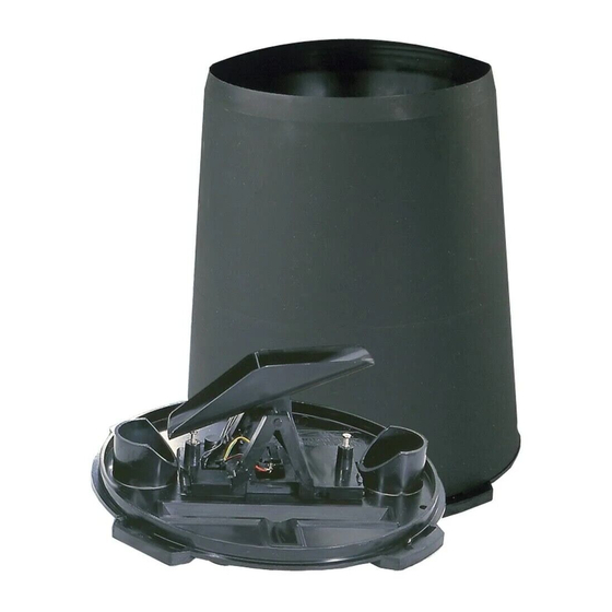
The Rain Collector II includes the following components. Please make sure you
have all listed components before continuing.
Rain Collector with Cable
The rain collector comes with the cone attached to the base. The standard
version of the rain collector comes with a 40' (12 m) cable. The industrial
version comes with a 16' (5 m) cable.
Four #8 x 3/4" Screws
Debris Screen
This screen is placed into the rain collector cone to help prevent debris
from clogging the funnel hole.
R
C
A I N
O L L E C T O R
S
T A N D A R D A N D
I
N S T A L L A T I O N
®
are also included in this manual. Instructions
I
N D U S T R I A L
M
A N U A L
®
, Weather Wiz-
Product #7852, 7852M, 7856, 7856M
II
Advertisement

Related Manuals for Davis Instruments Rain Collector


Summary of Contents for Davis Instruments Rain Collector
- Page 1 This instruction manual takes you step-by-step through the procedures required to install the Rain Collector II. The Rain Collector II is designed for use with any of Davis’ weather stations (with the exception of the Perception ® Station). Each station can display rainfall in either inches or millimeters. For greatest accuracy, however, use a rain collector which measures in the same unit in which you wish to display rainfall.
- Page 2 Note that the industrial versions of the rain collector also include a terminal block to which the rain collector cable is connected and a bubble level to help you insure that the rain collector is mounted on a level surface. Neither is pictured below.
-
Page 3: Tools And Materials Needed
(i.e., pulse) represents. Calibrated Rainfall= Number of pulses x (1/CAL) The default rainfall CAL of 100 works for the 0.01" rain collector. If you have a 0.01" rain collector you do not need to adjust CAL at all. - Page 4 You may want to reenter this amount after you test the rain collector. 1. Turn the rain collector upside down and remove the cone from the base by rotating the base until the latches on the cone line up with the latch openings in the base then lifting the base away from the cone.
-
Page 5: Rain Collector
Davis specifically disclaims any liabil- ity for injury or loss resulting from the installation or use of the Rain Collector II. Follow the instructions in this section to install your rain collector. Make sure you read see “Choosing a Location for the Rain Collector”... - Page 6 Typical Standard GroWeather/EnviroMonitor Installation The illustration below shows a typical standard rain collector installation for the GroWeather, Energy EnviroMonitor, or the Health EnviroMonitor. The rain collector cable attaches to connector S1 on the sensor interface module (SIM). YPICAL Page 6...
- Page 7 Typical Industrial GroWeather/EnviroMonitor Installation The illustration below shows a typical industrial rain collector installation for the GroWeather, Energy EnviroMonitor, or the Health EnviroMonitor. The rain collector cable attaches to connector S1 on the sensor interface module (SIM). YPICAL NDUSTRIAL Installing the Rain Collector II...
- Page 8 Be sure there is an unobstructed path for water runoff from the drain screens. The Rain Collector II contains a magnet-operated switch which may not operate correctly if you mount the rain collector on or near any object which attracts a magnet.
- Page 9 6. Fasten the base to the mounting surface using the #8 x 3/4" screws provided. 7. Attach the rain collector cable to the appropriate connector on the junction box/SIM. 8. To be certain the rain collector is functioning properly after installation, retest the unit as described “Testing the Rain Collector II”...
- Page 10 XTENDING ABLE If the cable length supplied with the rain collector is not long enough for your purposes, you may extend it. The maximum length of cable is 900 feet (270 m). Note that this length represents the total length from the rain collector to the console, including any length of cable from the junction box/SIM to the con- sole.
- Page 11 DJUSTING THE The Rain Collector II is calibrated at the factory so the bucket tips (and records rainfall) for each 0.01" (or 0.2 mm) of rain. To adjust the calibration slightly, use a 3/16" (or 5 mm) wrench to rotate the adjustment screws which are located underneath the bucket (see “Rain Collector Internal Components”...
- Page 12 The amount shown changes from inches to millimeters (or vice versa) and the symbol in the display changes from IN to MM (or vice versa). 5. To return to the original unit of measure, press UNITS again. Page 12 UNCTION AILY AINFALL OTAL AINFALL Rain Collector II...
- Page 13 To Set Total Rainfall You may enter a total rainfall amount to represent any rainfall which accumu- lated before you obtained the Rain Collector II. 1. Press RAIN once or twice to select total rainfall. 2. Use ENTER to set the total rainfall amount See “Using the Enter Key”...
- Page 14 Note: Keep in mind when testing the rain collector with older weather stations that the display adds 1 mm for each 5 tips of the bucket. Because the display rounds, however, the first change occurs after the bucket tips 3 times (0.6 mm rounded to 1 mm).
-
Page 15: Troubleshooting Guide
0.2 mm rain collector. Rainfall amount shown on console has a small error. Make sure the rain collector is mounted on a level surface. Use the adjustment screws (see “Adjusting the Rain Collector II” on page 11) to adjust the rain collector’s sensitivity, if necessary. - Page 16 Product Numbers: 7852, 7852M, 7856, 7856M Davis Instruments Part Number: 7395-024 Rain Collector, Standard & Industrial Rev. C Manual (7/7/99) This product complies with the essential protection requirements of the EC EMC Directive 89/336/EC. © Davis Instruments Corp. 1996. All rights reserved.
Need help?
Do you have a question about the Rain Collector and is the answer not in the manual?
Questions and answers