Table of Contents
Advertisement
The anemometer enables you to measure and display wind-related conditions
such as wind speed, wind direction, wind run, wind chill, and the
temperature-humidity-sun-wind index.
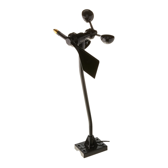
Components
The anemometer includes the components listed below. Please be sure you
have all listed components before continuing. The installation hardware kit
contains the items most commonly needed for the installation of the anemome-
ter. Which items you use from the kit depend on where you install your unit.
You may need to adapt or purchase additional hardware to fit your individual
requirements. Assess your installation and make sure you have all necessary
parts, tools, and materials before you begin.
Anemometer Arm with cable
Anemometer Base
Wind Cups
Wind Vane
Drip Rings
Anemometer Arm
with 40 feet (12.2 meters)
Anemometer
Base
S
T A N D A R D A N D
I
N D U S T R I A L
A
N E M O M E T E R
I
N S T A L L A T I O N
of cable
M
A N U A L
Wind Vane
Drip
Rings
Wind Cups
Product # 7911, 7914
Advertisement
Table of Contents

Related Manuals for Davis Instruments Anemometer


Summary of Contents for Davis Instruments Anemometer
- Page 1 Components The anemometer includes the components listed below. Please be sure you have all listed components before continuing. The installation hardware kit contains the items most commonly needed for the installation of the anemome- ter.
-
Page 2: Tools And Materials Needed
You will need the following tools and materials to install your anemometer: Cable Clips or Weather-Resistant Cable Ties Note: Make sure the clips or ties you use to secure the anemometer cable have screw holes or other means for mounting the cable. Do not use metal staples to secure the cables. -
Page 3: Assembling The Anemometer
Disconnect the cables when you are finished testing the anemometer. Assembling the Anemometer Attach the drip rings and the wind cups to the anemometer and check the mounting base orientation before you install it. The wind vane is attached after the anemometer has been installed. - Page 4 Installing the drip ring onto the anemometer control head Attaching the Wind Cups Before installing the anemometer, attach the wind cups. Wait until you have installed the anemometer before you attach the wind vane. Push the wind cups onto the smaller of the two stainless steel shafts at the end of the arm.
-
Page 5: Choosing The Best Anemometer Location
Use the following guidelines to determine the best location for your anemome- ter. Make sure you install the anemometer in a location where wind flow is unobstructed by trees and nearby buildings. For the most accurate readings, the anemometer should be mounted at least 4 feet (1.2 m) above the roof line. -
Page 6: Installing The Anemometer
Installing the Anemometer Installing the Anemometer Use the following procedures to mount the anemometer. Installing on a Sensor Mounting Arm Consult the Sensor Mounting Arm manual for instructions. You will need to return to this instruction manual after installing onto the Sensor Mounting Arm for instructions on attaching the wind vane (see “Attaching the Wind Vane”... - Page 7 Use stainless steel hose clamps to attach the mounting base to masts or pipes larger than 1 1/4” diameter. Use two stainless steel hose clamps large enough to fit around the mast or pipe and the anemometer base. You may purchase hose clamps at your local hard- ware store.
- Page 8 You may wish to have a friend or family member on the ground do this for you. Or, you may wish to bring the console and SIM/junc- tion box onto the roof with you. Connect the anemometer cable to the SIM/junction box. Press WIND key on console if necessary to display wind direction in degrees.
-
Page 9: Maintenance
Securing the Cable To prevent fraying or cutting of the anemometer cable where it is exposed to weather, it is very important that you secure it so it doesn’t whip about in the wind. -
Page 10: Troubleshooting
• Check for broken wire along length of anemometer cable. Carefully check the places where the cable has been secured. Note: If these steps do not solve the problem, the problem is probably with the anemometer. Call Davis Tech- nical Support for return authorization. -
Page 11: Specifications
Contacting Davis Instruments Technical Support If you have any questions about our products, please call Davis Technical Sup- port. We’ll be glad to help. Most questions can be answered while you’re on the phone. You can also email us for support, or visit our website. Sorry, we are unable to accept collect calls. - Page 12 Rev. B Manual (3/14/2001) This product complies with the essential protection requirements of the EC EMC Directive 89/336/EC. © Davis Instruments Corp. 2001. All rights reserved. 3465 Diablo Avenue, Hayward, CA 94545-2778 510-732-9229 • Fax: 510-732-9188 E-mail: info@davisnet.com • www.davisnet.com...
Need help?
Do you have a question about the Anemometer and is the answer not in the manual?
Questions and answers