Table of Contents
Advertisement
Quick Links
Advertisement
Table of Contents

Related Manuals for Netberg Aurora 750


Summary of Contents for Netberg Aurora 750
- Page 1 The Aurora 750 switch installation guide...
- Page 2 The Aurora 750 switch installation guide...
-
Page 3: Table Of Contents
2.7. Grounding the Switch .................... 11 2.8. Rack-mount Safety Precautions ................12 2.9. Console port ......................13 2.10. Verifying Switch Operation ................... 14 3. Netberg Aurora 750 switch ....................15 3.1. Specification ......................17 3.2. Supported Cables and Transceivers ............... 19... - Page 4 List of Figures 2.1. Front brackets installation ....................4 2.2. Rack installation ......................5 2.3. Transceivers and cables ....................6 2.4. Power Supply ........................9 3.1. Aurora 750 front view ....................15 3.2. Aurora 750 rear view ..................... 16...
- Page 5 List of Tables 2.1. Console cable pin definition ................... 13 3.1. Front panel features ...................... 15 3.2. Rear panel features ....................... 16...
-
Page 6: Introduction
This guide is to assist the reader with the most basic form of installation and cable connection to our switches. As there is more than one switch in the Aurora series, the actual port placement might slightly differ, however, the installation and connection logic are the same for all Netberg switches. -
Page 7: Hardware Installation
Chapter 2. Hardware Installation... -
Page 8: Installation Guidelines
Hardware Installation 2.1. Installation Guidelines This section will discuss the hardware installation guidelines that administrators must follow in or- der to properly and safely install this switch into the appropriate environment. -
Page 9: Installation Into A Rack
Hardware Installation 2.2. Installation into a Rack The switch can be mounted in a standard 19"(1U) rack using the provided mounting brackets. The following section will explain how to install the rack-mount brackets onto the switch and then mount the switch into a standard 2U rack-mount unit. 1. - Page 10 Hardware Installation Figure 2.2. Rack installation /3 3 /3 4 R ES Illustrations are for reference purposes only. Actual switch and cabinet posts may dif- fer.
-
Page 11: Installing Transceivers And Cables Into The Switch Ports
Hardware Installation 2.3. Installing Transceivers and cables into the Switch Ports Figure 2.3. Transceivers and cables 2.3.1. SFP+/SFP28 Port Connection (LC Type Connec- tor) The Small Form-Factor Pluggable Plus (SFP+) port is the second generation of the SFP intercon- nect system designed for 10Gb/s data rate. The SFP+ ports support 10-gigabit IEEE 802.3ae Eth- ernet for fiber mediums. -
Page 12: Qsfp+/Qsfp28 Port Connection
Hardware Installation 2.3.2. QSFP+/QSFP28 Port Connection QSFP+ (Quad SFP) ports which support 40G/per port or fan out to 4x10G by using the fan out DAC cable. QSFP28 (Quad SFP) ports which support 100G/per port or fan out to 4x25G by using the fan out DAC cable. -
Page 13: Fan Modules
Hardware Installation 2.4. Fan Modules The fan module is a field replaceable unit and can be replaced during operations as long as the re- maining modules are installed and operating. Replacing fan modules 1. Loosen the captive screw securing the fan module. 2. -
Page 14: Power Supply
Hardware Installation 2.5. Power supply Equipped with two supply modules, the switch can operate with either one or two power supply modules. If the switch uses two power supply modules, you can hot-swap one of the PSU during the operations. Figure 2.4. Power Supply One PSU is enough for a fully loaded chassis. -
Page 15: Connect The Power Cable
Hardware Installation 2.6. Connect the Power Cable Connect one end of the AC power cord, included in the package, into the grounded electrical outlet at the site and insert the other end of the AC power cord into the AC power receptacle of the AC power supply module on the back panel of the switch. -
Page 16: Grounding The Switch
Hardware Installation 2.7. Grounding the Switch It is recommended that a compliant system is installed as part of the chassis to reduce or prevent the risk of shock hazards, greatly reduce the risk of equipment damage or reduce the potential of data corruption. -
Page 17: Rack-Mount Safety Precautions
Hardware Installation 2.8. Rack-mount Safety Precautions For your protection, observe the following rack-mount safety precautions when setting up your equipment: • Elevated Operating Ambient - If installed in a closed or multi-unit rack assembly, the operating ambient temperature of the rack environment may be greater than room ambient. Therefore, consideration should be given to installing the equipment in an environment compatible with the maximum ambient temperature (Tma) specified by the manufacturer. -
Page 18: Console Port
Hardware Installation 2.9. Console port The console port is used for setting up and managing the switch via a connection to a console ter- minal or PC using a terminal emulation program. The switch provides 2 types of console port interface: RJ45 or micro USB type B; both are used to configure the switch. -
Page 19: Verifying Switch Operation
Hardware Installation 2.10. Verifying Switch Operation Verify basic switch operation by checking the system LEDs. When a NOS operating normally, the PSU1/PSU2, FAN, and SYS LEDs should all display green. -
Page 20: Netberg Aurora 750 Switch
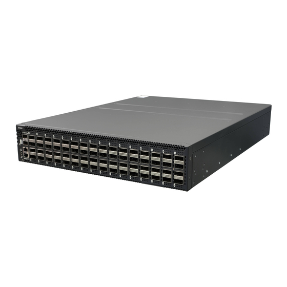
Chapter 3. Netberg Aurora 750 switch The switch chassis is equipped with the following ports: • 64x 100G QSFP28 ports supporting an optical transceiver, active optical cables, or direct-at- tached cable to connect the QSFP28 port to the hosts (uplink connections) •... - Page 21 Netberg Aurora 750 switch Figure 3.2. Aurora 750 rear view Table 3.2. Rear panel features Description Description 2x PSU modules 4x fan modules PSU status LED Fan status LED...
-
Page 22: Specification
Netberg Aurora 750 switch 3.1. Specification System specification Ports • 64x 100/40GbE QSFP28 ports in 1 RU • Up to 256x 25/10G SFP28 port via break-out cables • 2x 10G SFP+ ports • 1x RJ-45 out-of-band (10/100/1000) management • 1x RJ-45 console (RS232) •... - Page 23 Netberg Aurora 750 switch • SONiC...
-
Page 24: Supported Cables And Transceivers
Netberg Aurora 750 switch 3.2. Supported Cables and Transceivers See the following table for the list of supported cables and transceivers. Distance Description Note 40/100G Direct Attach Copper (DAC) cable QSFP28 to QSFP28 40/100G DAC Fan Out cable QSFP28 to 4...
Need help?
Do you have a question about the Aurora 750 and is the answer not in the manual?
Questions and answers