Table of Contents
Advertisement
Quick Links
Advertisement
Table of Contents

Related Manuals for Netberg Aurora 615


Summary of Contents for Netberg Aurora 615
- Page 1 The Aurora 615 switch installation guide...
- Page 2 The Aurora 615 switch installation guide...
-
Page 3: Table Of Contents
2.7. Grounding the Switch .................... 11 2.8. Rack-mount Safety Precautions ................12 2.9. Console port ......................13 3. Netberg Aurora 615 switch ....................14 3.1. Button and System LED Information ............... 16 3.2. Specification ......................19 3.3. Supported Cables and Transceivers ............... 21... - Page 4 2.4. Inserting the fan module ....................7 2.5. Removing the PSU module ..................... 8 2.6. Inserting the PSU module ....................9 3.1. Aurora 615 front view ....................14 3.2. Aurora 615 rear view ..................... 14 3.3. Aurora 615 side view ..................... 15 3.4.
- Page 5 List of Tables 2.1. Console cable pin definition ................... 13 3.1. Front panel features ...................... 14 3.2. Rear panel features ....................... 14 3.3. Side panel features ....................... 15 3.4. Front panel features ...................... 16 3.5. System LED Indicator definitions ..................16 3.6.
-
Page 6: Introduction
This guide is to assist the reader with the most basic form of installation and cable connection to our switches. As there is more than one switch in the Aurora series, the actual port placement might slightly differ, however, the installation and connection logic are the same for all Netberg switches. -
Page 7: Hardware Installation
Chapter 2. Hardware Installation... -
Page 8: Installation Guidelines
Hardware Installation 2.1. Installation Guidelines This section will discuss the hardware installation guidelines that administrators must follow in or- der to properly and safely install this switch into the appropriate environment. -
Page 9: Installation Into A Rack
Hardware Installation 2.2. Installation into a Rack The switch can be secured in a standard 19"(1U) rack using the provided mounting ears. The fol- lowing section will explain how to install the rack-mount ears onto the switch and then mount the switch into a standard 1U rack-mount unit. -
Page 10: Installing Transceivers And Cables Into The Switch Ports
Hardware Installation 2.3. Installing Transceivers and Cables into the Switch Ports Figure 2.2. Transceivers and cables 2.3.1. SFP+/SFP28 Port Connection (LC Type Connec- tor) The Small Form-Factor Pluggable Plus (SFP+) port is the second generation of the SFP intercon- nect system designed for 10Gb/s data rate. The SFP+ ports support 10-gigabit IEEE 802.3ae Eth- ernet for fiber mediums. -
Page 11: Qsfp+/Qsfp28 Port Connection
Hardware Installation 2.3.2. QSFP+/QSFP28 Port Connection QSFP+ (Quad SFP) ports which support 40G/per port or fan out to 4x10G by using the fan out DAC cable. QSFP28 (Quad SFP) ports which support 100G/per port or fan out to 4x25G by using the fan out DAC cable. -
Page 12: Fan Modules
Hardware Installation 2.4. Fan Modules The fan module is a field replaceable unit and can be replaced during operations as long as the re- maining modules are installed and operating. Replacing fan modules 1. Press the retaining tab on the system fan module in the direction as indicated. 2. -
Page 13: Power Supply
Hardware Installation 2.5. Power supply Equipped with two supply modules, the switch can operate with either one or two power supply modules. If the switch uses two power supply modules, you can hot-swap one of the PSU during the operations. Even if one of the two power supplies has failed, or is not in use, do not pull out the power supply from the chassis. - Page 14 Hardware Installation Figure 2.6. Inserting the PSU module The AC power connector is a standard three-pronged connector. The switch automatically adjusts its power setting to any supply voltage in the range from 100-240 VAC at 50-60 Hz.
-
Page 15: Connect The Power Cable
Hardware Installation 2.6. Connect the Power Cable Connect one end of the AC power cord, included in the package, into the grounded electrical outlet at the site and insert the other end of the AC power cord into the AC power receptacle of the AC power supply module on the back panel of the switch. -
Page 16: Grounding The Switch
Hardware Installation 2.7. Grounding the Switch It is recommended that a compliant system is installed as part of the chassis to reduce or prevent the risk of shock hazards, greatly reduce the risk of equipment damage or reduce the potential of data corruption. -
Page 17: Rack-Mount Safety Precautions
Hardware Installation 2.8. Rack-mount Safety Precautions For your protection, observe the following rack-mount safety precautions when setting up your equipment: • Elevated Operating Ambient - If installed in a closed or multi-unit rack assembly, the operating ambient temperature of the rack environment may be greater than room ambient. Therefore, consideration should be given to installing the equipment in an environment compatible with the maximum ambient temperature (Tma) specified by the manufacturer. -
Page 18: Console Port
Hardware Installation 2.9. Console port The console port is used for setting up and managing the switch via a connection to a console ter- minal or PC using a terminal emulation program. You can connect the switch to a terminal or PC using the supplied console cable (RJ-45 male to RS-232 female cable) for serial communication. -
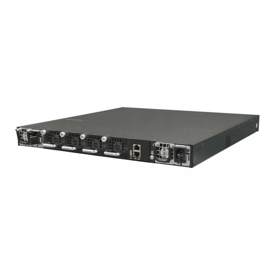
Page 19: Netberg Aurora 615 Switch
Chapter 3. Netberg Aurora 615 switch The switch chassis is equipped with the following ports: • 48x 25G SFP28 + 8x 100G QSFP28 ports supporting an optical transceiver, active optical ca- bles, or direct-attached cable to connect the QSFP28 port to the hosts (uplink connections) •... - Page 20 Netberg Aurora 615 switch Description 4x system fans Figure 3.3. Aurora 615 side view Table 3.3. Side panel features Description Mounting holes...
-
Page 21: Button And System Led Information
Netberg Aurora 615 switch 3.1. Button and System LED Information This switch is equipped with SFP28 port link/activity LEDs (1 per port), QSFP28 port link/activity LEDs (4 per port), one activity LED and one link LED for the management port, and a health/status LED indicators on the front panel. - Page 22 Netberg Aurora 615 switch Color Status Description C: Console Green/ Amber SW control The SW control function depends on the software installed. The description above is only for reference. Table 3.6. QSFP28 Per-Port Four LEDs Configuration definitions Location Description LED 1 Per-port x 4 Lan SerDes (40/100G)
-
Page 23: Rear Panel Features
Netberg Aurora 615 switch LED Type Color Status Function Cyan (Aquama- Solid light When there is a secure connection rine) (or link) to 50Gbps Ethernet device at any of the ports. Blinking When there is reception or transmis- sion of data occurring at 50Gbps. -
Page 24: Specification
Netberg Aurora 615 switch 3.2. Specification System specification Ports • 48x 10/25GbE SFP28 + 8x 100/40GbE QSFP28 ports in 1 RU • Up to 80x 25/10G SFP28 port via break-out cables • 1x RJ-45 out-of-band (10/100/1000) management • 1x RJ-45 console (RS232) •... - Page 25 Netberg Aurora 615 switch • Front-to-Back airflow Dimensions (DxWxH) 470 x 440 x 44 mm Environment Operating temperature: 0~40°C Operating humidity 20-95% maximum relative humidity (non-condensing) Compatible NOS • Open Network Linux • SONiC...
-
Page 26: Supported Cables And Transceivers
Netberg Aurora 615 switch 3.3. Supported Cables and Transceivers See the following table for the list of supported cables and transceivers. Distance Description Note 40/100G Direct Attach Copper (DAC) cable QSFP28 to QSFP28 40/100G DAC Fan Out cable QSFP28 to 4...
Need help?
Do you have a question about the Aurora 615 and is the answer not in the manual?
Questions and answers