Table of Contents
Advertisement
Quick Links
Advertisement
Table of Contents

Related Manuals for Netberg Aurora 820


Summary of Contents for Netberg Aurora 820
- Page 1 The Aurora 820 switch installation guide...
- Page 2 The Aurora 820 switch installation guide...
-
Page 3: Table Of Contents
2.9. Rack-mount Safety Precautions ................17 2.10. The Warranty VOID Label ..................18 2.11. Console port ......................19 3. Netberg Aurora 820 switch ....................20 3.1. Button and System LED Information ............... 22 3.2. Specification ......................26 3.3. Supported Cables and Transceivers ............... 27... - Page 4 2.13. PSU modules location ....................13 2.14. Removing the PSU module ..................14 2.15. Inserting the PSU module .................... 14 3.1. Aurora 820 front view ....................20 3.2. Port numbering ......................20 3.3. Aurora 820 rear view ..................... 20 3.4. Front Panel Button and LED ..................22...
- Page 5 List of Tables 2.1. Serial port pin definition ....................19 3.1. Front panel features ...................... 20 3.2. Rear panel features ....................... 21 3.3. Front panel features ...................... 22 3.4. Rear panel features ....................... 22 3.5. LED definition ....................... 23 3.6. Optics and Cables Support .................... 27...
-
Page 6: Introduction
This guide is to assist the reader with the most basic form of installation and cable connection to our switches. As there is more than one switch in the Aurora series, the actual port placement might slightly differ, however, the installation and connection logic are the same for all Netberg switches. -
Page 7: Intended Application Uses
Introduction 1.1. Intended Application Uses This product was evaluated as Information Technology Equipment (ITE), which may be installed in offices, schools, computer rooms, and similar commercial type locations. Other than an ITE appli- cation, this product’s suitability for different product categories and environments (such as medical, industrial, residential, alarm systems, and test equipment) may require further evaluation. -
Page 8: Hardware Installation
Chapter 2. Hardware Installation... -
Page 9: Installation Guidelines
Hardware Installation 2.1. Installation Guidelines This section will discuss the hardware installation guidelines that administrators must follow in or- der to properly and safely install this switch into the appropriate environment. -
Page 10: Installation Into A Rack
Hardware Installation 2.2. Installation into a Rack The switch can be secured in a standard 19"(1U) rack using the provided mounting ears. The fol- lowing section will explain how to install the rack-mount ears onto the switch and then mount the switch into a standard 1U rack-mount unit. -
Page 11: Rail Kit Installation
Hardware Installation 2.3. Rail Kit Installation 2.3.1. An optional rail kit installation directions. 1. Push the tab in the direction as indicated to detach the inner rail from the slide. Figure 2.2. Detaching the Inner Rail 2. Align the inner rail to the retaining posts on the side of the switch. 3. - Page 12 Hardware Installation Figure 2.4. Attaching Outer Rail on the Rear to the Rack 6. Press the retaining clip on the front end as indicated. 7. Attach the outer rail to the rack on the front end, and lock it by releasing the clip till it clicks into place with rack.
-
Page 13: To Remove The Switch From The Rack
Hardware Installation Figure 2.6. Pushing Switch into the Rack 9. Tighten screws on both sides to lock switch on the rack. Figure 2.7. Installing Switch into the Rack 2.3.2. To remove the switch from the rack 1. Push the tabs on both sides of the inner rails in the direction as indicated. 2. - Page 14 Hardware Installation Figure 2.8. Removing Switch from the Rack...
-
Page 15: Installing Transceivers And Cables Into The Switch Ports
Hardware Installation 2.4. Installing Transceivers and Cables into the Switch Ports Figure 2.9. Transceivers and cables 2.4.1. QSFP-DD Port Connection QSFP-DD ports which support 400G/per port or fan out to 4x100G by using the fan-out DAC cable. 1. Slide the QSFP-DD module into a QSFP-DD port. Ensure the QSFP-DD module is positioned correctly before installing it into the port. -
Page 16: Fan Modules
Hardware Installation 2.5. Fan Modules This product contains six system fan modules which are located at the rear of the chassis. The location of the system fan modules is shown below: Figure 2.10. Fan modules location The fan module is a field replaceable unit and can be replaced during operations as long as the re- maining modules are installed and operating. - Page 17 Hardware Installation Figure 2.12. Inserting the fan module...
-
Page 18: Power Supply
Hardware Installation 2.6. Power supply Equipped with two supply modules, the switch can operate with either one or two power supply modules. If the switch uses two power supply modules, you can hot-swap one of the PSU during the operations. Even if one of the two power supplies has failed, or is not in use, do not pull out the power supply from the chassis. - Page 19 Hardware Installation Figure 2.14. Removing the PSU module 3. Align the PSU with the switch bay. 4. Slide the PSU into the switch and push until it is flush with the bay. The retaining clip should snap. Figure 2.15. Inserting the PSU module The AC power connector is a standard three-pronged connector. The switch automatically adjusts its power setting to any supply voltage in the range from 100-240 VAC at 50-60 Hz.
-
Page 20: Connect The Power Cable
Hardware Installation 2.7. Connect the Power Cable Connect one end of the AC power cord, included in the package, into the grounded electrical outlet at the site and insert the other end of the AC power cord into the AC power receptacle of the AC power supply module on the back panel of the switch. -
Page 21: Grounding The Switch
Hardware Installation 2.8. Grounding the Switch It is recommended that a compliant system is installed as part of the chassis to reduce or prevent the risk of shock hazards, greatly reduce the risk of equipment damage or reduce the potential of data corruption. -
Page 22: Rack-Mount Safety Precautions
Hardware Installation 2.9. Rack-mount Safety Precautions For your protection, observe the following rack-mount safety precautions when setting up your equipment: • Elevated Operating Ambient - If installed in a closed or multi-unit rack assembly, the operating ambient temperature of the rack environment may be greater than room ambient. Therefore, consideration should be given to installing the equipment in an environment compatible with the maximum ambient temperature (Tma) specified by the manufacturer. -
Page 23: The Warranty Void Label
Hardware Installation 2.10. The Warranty VOID Label There is a warranty VOID label sticked on the chassis cover. When this label is removed or de- stroyed, the warranty will be void. -
Page 24: Console Port
Hardware Installation 2.11. Console port The console port is used for setting up and managing the switch via a connection to a console ter- minal or PC using a terminal emulation program. You can connect the switch to a terminal or PC using the supplied console cable (RJ-45 male to RS-232 female cable) for serial communication. -
Page 25: Netberg Aurora 820 Switch
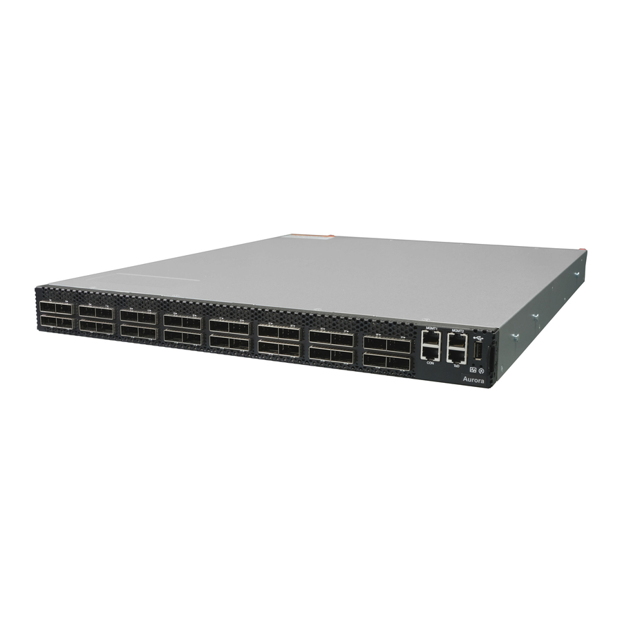
Chapter 3. Netberg Aurora 820 switch The switch chassis is equipped with the following ports: • 32x 400G QSFP-DD ports supporting an optical transceiver, active optical cables, or direct-at- tached cable to connect the QSFP-DD port to the hosts • 2 Management ports enables you to manage the switch operation using an RJ-45 Ethernet ca- •... -
Page 26: Rear Panel Features
Netberg Aurora 820 switch Table 3.2. Rear panel features Description AC Power Socket 2 AC Power Socket 1 #1-6 Fans... -
Page 27: Button And System Led Information
Netberg Aurora 820 switch 3.1. Button and System LED Information This switch is equipped with 400G QSFP-DD port link/activity LEDs (4 per port), and health/status LED indicator, and a reset button on the front panel. These LEDs allow constant monitoring of ba- sic system functions while the switch is operating and provide visual indication of system status. -
Page 28: Led Definition
Netberg Aurora 820 switch The detailed LED information is shown below: Table 3.5. LED definition Function Color Status Description Health/status LED (bi- Green Lit: Switch ready color) (525nm) Blinking(0.5Hz): Bootloader execution Blinking (4Hz): BIOS ready Off: System not powered Amber(Green Lit: One of PSUs unpowered or cau-... - Page 29 Netberg Aurora 820 switch Function Color Status Description QSFP-DD Status Green Lit: 200/100/40G link is up (split out LED-2 (bi-color) (520-535nm) 4-LANES/PORT mode lane 5-8) 100/50G link is up (split out 2- LANES/PORT mode lane 3-4) Blinking(2Hz): 200/100/40G activity (split out 4-...
- Page 30 Netberg Aurora 820 switch Function Color Status Description Off: 100/50G link is down (split out 2- LANES/PORT mode lane 7-8) Amber(Green Lit: 50/25/10G lane 7 or 8 link is up +Red) (split out 1-LANE/PORT mode) Blinking(2Hz): 50/25/10G lane 7 or 8 activity...
-
Page 31: Specification
Netberg Aurora 820 switch 3.2. Specification System specification Ports • 32x 400GbE QSFP-DD ports in 1 RU • Up to 128x100G port via break-out cables • 2x RJ-45 out-of-band (10/100/1000) management • 1x RJ-45 console (RS232) • 1x USB • 1x ToD Front IO •... -
Page 32: Supported Cables And Transceivers
Netberg Aurora 820 switch 3.3. Supported Cables and Transceivers See the following table for the list of supported cables and transceivers, up to 12W per module (Power Class 6). Table 3.6. Optics and Cables Support Interface Type Range 100GBASE DAC 100GBASE AOC...
Need help?
Do you have a question about the Aurora 820 and is the answer not in the manual?
Questions and answers