Table of Contents
Advertisement
Assembly Instructions
& User's Manual
MULTIFUNCTION COOKER
Model No.: TF2112712-OG
Ref. Style: FSOGBG4008
Please keep this instruction manual for future reference
Customer Service: 1 – 888 – 922 – 2336
7:00am to 12:00am CST (daily)
Live Chat at: www.academy.com
Email: customerservice@academy.com
----------------------OR--------------------
Customer Service: 1 – 888 – 837 – 1380, 8:00am to 5:00pm, Pacific Standard Time,
Monday to Friday,
Email: customerservice@rankam.com
(Made in China)
Advertisement
Table of Contents

Related Manuals for Outdoor Gourmet TF2112712-OG


Summary of Contents for Outdoor Gourmet TF2112712-OG
- Page 1 Assembly Instructions & User’s Manual MULTIFUNCTION COOKER Model No.: TF2112712-OG Ref. Style: FSOGBG4008 Please keep this instruction manual for future reference Customer Service: 1 – 888 – 922 – 2336 7:00am to 12:00am CST (daily) Live Chat at: www.academy.com Email: customerservice@academy.com ----------------------OR-------------------- Customer Service: 1 –...
-
Page 2: Table Of Contents
Read and follow all warnings and instructions before assembling and using the appliance. Follow all warnings and instructions when using the appliance. Keep this manual for future reference. This appliance is NOT for frying turkeys. For Outdoor Use Only. TF2112712-OG Page 1 of 23 20190704-Ver.1.2... -
Page 3: Warnings
1. Do not store or use gasoline or other flammable liquids or vapors in the vicinity of this or any other appliance. 2. An LP cylinder not connected for use shall not be stored in the vicinity of this or any other appliance. TF2112712-OG Page 2 of 23 20190704-Ver.1.2... - Page 4 Failure to follow these instructions could result in fire, explosion or burn hazard which could cause property damage, personal injury or death. WARNING This Appliance is NOT intended for commercial use. WARNING This Appliance is NOT for Frying Turkeys. TF2112712-OG Page 3 of 23 20190704-Ver.1.2...
- Page 5 NONCOMBUSTIBLE SURFACE in an area clear of combustible material. An asphalt surface (blacktop) is not acceptable for this purpose. DO NOT leave the appliance unattended. Keep children and pets away from the appliance at all times. TF2112712-OG Page 4 of 23 20190704-Ver.1.2...
- Page 6 If you see, smell, or hear escaping gas, immediately get away from the LP tank / appliance and call your FIRE DEPARTMENT. All spare LP tanks must have safety caps installed on the LP tank outlet. TF2112712-OG Page 5 of 23 20190704-Ver.1.2...
- Page 7 Do not release liquid propane (LP) gas into the atmosphere. This is a hazardous practice. To remove gas from LP tank, contact an LP dealer or call a local FIRE DEPARTMENT for assistance. Check the telephone directory under “GAS Companies” for nearest certified LP dealers. TF2112712-OG Page 6 of 23 20190704-Ver.1.2...
- Page 8 The regulator will seal on the back-check feature in the LP tank valve, resulting in some resistance. An additional one-half to three quarters turn is required to complete connection. TIGHTEN BY HAND ONLY – DO NOT USE TOOLS. TF2112712-OG Page 7 of 23 20190704-Ver.1.2...
-
Page 9: Leak Test
Customer Service Center at 1 – 888 – 922 – 2336 or 1 – 888 – 837 – 1380. Use only replacement parts specified by manufacturer. 6. Always close LP tank valve after performing tank test by turning hand wheel clockwise. TF2112712-OG Page 8 of 23 20190704-Ver.1.2... -
Page 10: Lighting Instructions
If there is evidence of abrasion, wear, cuts or leaks, the hose assembly must be replaced prior to the appliance being put into operation. The replacement hose assembly shall be that specified by the manufacturer. TF2112712-OG Page 9 of 23 20190704-Ver.1.2... -
Page 11: Maintenance & Cleaning Instructions
To keep the appliance clear and free from gasoline and other flammable vapors and liquids. Not obstructing the flow of combustion and ventilation air. Keeping the ventilation opening(s) of the cylinder enclosed free and clear from debris. TF2112712-OG Page 10 of 23 20190704-Ver.1.2... -
Page 12: Tools Required
Replace corroded or damaged burners that would emit excess gas. For cooking surfaces like pots and pans: Clean the cooking surface with soapy water and a nylon cleaning pad. Tools Required Phillips screwdriver (not included) Adjustable wrench (not included) TF2112712-OG Page 11 of 23 20190704-Ver.1.2... -
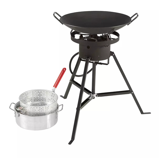
Page 13: Product Diagram
PRODUCT DIAGRAM TF2112712-OG Page 12 of 23 20190704-Ver.1.2... -
Page 14: Parts List
Qty: 1pc Qty: 1pc Qty: 1pc 7. Leg Brace 8. Pole 9. Legs Connecting Part Qty: 3pcs Qty: 1pc Qty: 1pc 10. Discada 11. Thermometer 12. Fish Basket Qty: 1pc Qty: 1pc Qty: 1pc TF2112712-OG Page 13 of 23 20190704-Ver.1.2... -
Page 15: Hardware List
Qty: 1pc HARDWARE LIST Part# Description Diagram Qty. Bolt (M5 x 12) Flange Nut (M5) Bolt (M5 x 30) Locking Nut (M5) L Pin Cotter Pin Bolt M5 x 10 Nut M5 Tooth Washer TF2112712-OG Page 14 of 23 20190704-Ver.1.2... - Page 16 Step 1: Attach the Support Bracket (2) to the Fire Ring (1) by using 6pcs of Bolt A and Flange Nut B. Step 2: Attach the Burner Bracket (5) to the fire ring by using 4pcs of Bolt A and Flange Nut TF2112712-OG Page 15 of 23 20190704-Ver.1.2...
- Page 17 Step 3: Remove the nut (on the threaded pin) of the Burner (4) and attach the burner to the burner bracket. Fasten the burner by using the removed nut. Step 4: Attach the Pole (8) to the burner bracket by using 2pcs of Bolt A and Flange Nut B. TF2112712-OG Page 16 of 23 20190704-Ver.1.2...
- Page 18 Step 5: Attach the Leg Brace (7) to Legs Connecting Part (9) by using 3pcs of Bolt C and Nut D. Step 6: Put the L Pin (E) through the hole of pole, attach the Cotter Pin (F) to the pin. TF2112712-OG Page 17 of 23 20190704-Ver.1.2...
- Page 19 Step 7: Attach the Leg (3) to the leg brace by using 3pcs of Bolt C and Nut D. Step 8: Attach the Legs (3) to the fire ring by using 3pcs of Bolt C and Nut D. TF2112712-OG Page 18 of 23...
- Page 20 Step 9: Fasten the Regulator (6) outlet to the burner inlet per following shown. Step 10: Attach the Fish Basket Handle (13) to the Fish Basket (12) by using the bolt G, nut H and tooth washer I. TF2112712-OG Page 19 of 23 20190704-Ver.1.2...
- Page 21 The provided Thermometer (11) must be used during frying. Step 12: The Gas Regulator must be hanged with Regulator Hook (6a) when not in use. DO NOT leave the regulator on the floor. TF2112712-OG Page 20 of 23 20190704-Ver.1.2...
- Page 22 Step 13: To fold the fryer stand. Press the button at the bottom of pole per STEP 1 shown. Fold the legs per the STEP 2 shown until the legs connecting part pass through the button at the top of the pole. TF2112712-OG Page 21 of 23 20190704-Ver.1.2...
-
Page 23: Trouble Shooting
LP tank valve until the valve is fully open. Light all burners and observe the temperature. Burner is too 1. Damaged or faulty regulator. 1. Replace the damaged parts with hot. factory authorized component. TF2112712-OG Page 22 of 23 20190704-Ver.1.2... -
Page 24: Warranty Information
/ at 1 – 888 – 837 – 1380, 8:00am to 5:00pm, Pacific Standard Time, Monday to Friday RANKAM (CHINA) MANUFACTURING COMPANY LIMITED 18/F., New Lee Wah Centre, 88 Tokwawan Road, Kowloon, Hong Kong TF2112712-OG Page 23 of 23 20190704-Ver.1.2...
Need help?
Do you have a question about the TF2112712-OG and is the answer not in the manual?
Questions and answers