
Related Manuals for Secureye S-24GE-M-2UG-400W-AI-VLAN


Summary of Contents for Secureye S-24GE-M-2UG-400W-AI-VLAN
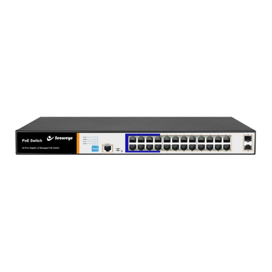
- Page 1 User Manual S-24GE-M-2UG-400W-AI-VLAN 24 Port Gigabit Layer 2 Managed AI PoE Switch...
- Page 2 Installation manual introduction The Product installation manual mainly describes S-24GE-M-2UG-400W-AI-VLAN AI PoE switch hardware features, installation methods, and precautions during the installation. This manual includes the following chapters: Chapter 1: Product Introduction. Briefly describes the basic features of the switch and the appearance details.
-
Page 3: Chapter 1 Product Introduction
Chapter 1 Product Introduction 1.1 Product Introduction S-24GE-M-2UG-400W-AI-VLAN is Layer 2 Managed AI PoE switch designed for security transmission and WIFI coverage. It can satisfy the POE power supply requirements of WIFI AP, IP camera, WIFI bridge, IP phone and other types of equipment. - Page 4 DC power supply technology. These devices that accept DC power supply are called powered devices (PD, Powered Device) 1.2 Packing List Open the package and check the list below Commodity Quantity Description PoE switch 1 pc Power cord 1 pc Optional Bracket 2 pcs...
- Page 5 Indicators S-24GE-M-2UG-400W-AI-VLAN The indicator working status is shown as following table: Work Indicator Title color Description status Solid Power is normal Power No power, the power switch is indicator not turned on, power supply is abnormal The corresponding RJ45 port is...
- Page 6 RJ45 Port S-24GE-M-2UG-400W-AI-VLAN supports 24 10/100/1000 Mbps ports, all supporting IEEE802.3af and IEEE802.3at standard POE power supply. SFP Port S-24GE-M-2UG-400W-AI-VLAN provides 2 Gigabit SFP optical module expansion slots (25, 26) for plugging Gigabit SFP modules RST Button When the switch is powered on, press the button with needle and release the device to enter the restart state.
-
Page 7: Chapter 2 Product Installation
Power socket The power supply to the switch S-24GE-M-2UG-400W-AI-VLAN should be 100- 240V~ 50/60Hz AC power. Ground terminal Please use a wire to ground so that preventing lightning strikes, to avoid product lightning strikes and extend the life of the product. - Page 8 The switch can work normally under the correct power supply. Please confirm that the power supply voltage matches the voltage indicated by the switch. Before powering on the switch, please make sure that the power circuit is not overloaded, so as not to affect the normal operation of the switch and even cause unnecessary damage.
- Page 9 Products with this mark are only suitable for safe use in areas below 2000m. Dust-proof Dust falling on the surface of the switch can cause electrostatic adsorption and poor contact of the metal contacts. Although the device itself has made certain measures in anti-static, when the static electricity exceeds a certain strength, it will still cause fatal damage to the electronic components on the internal circuit board.
- Page 10 Lightning protection needs When a lightning strike occurs, a strong current is generated in an instant, and the air in the discharge path is instantaneously heated to 20,000 degrees Celsius, and an instantaneous large current is enough to cause fatal damage to the electronic device. For better lightning protection, please note the following: Confirm that the rack is in good contact with the ground.
-
Page 11: Chapter 3 Hardware Connection
19-inch standard rack installation S-24GE-M-2UG-400W-AI-VLAN is designed according to the standard 19-inch rack size, you can easily install to the rack, the specific installation steps as follows: Check rack grounding and stability. Install the two L-brackets in the accessory on each side of the switch panel and secure with the screws provided in the accessory. - Page 12 3.1 RJ45 port connection Connect the RJ45 port of the switch and the corresponding network device via cables, the POE power supply function of the switch is default enabled on the downlink port of the switch, which can be used for IEEE802.3af or IEEE802.3at standards powered devices such as APs, bridges, and network cameras.
- Page 13 Do not connect the RJ45 port to the phone line. 3.2 SFP Port connection S-24GE-M-2UG-400W-AI-VLAN SFP port only support Gigabit fiber module. Recommended use of standard SFP module products The process of installing a fiber module on a switch is as follows:...
-
Page 14: Device Initialization
be less than 10cm. Ensure the cleanliness of the fiber surface. Please do not look directly into the optical fiber connector with your eyes as this may cause eye injury. 3.3 Check before power on Check whether the outlet power supply meets the switch specifications. Check the power, switches, racks and other equipment have been properly grounded. - Page 15 3.5 Web Login Step1、In the normal operation of the device, connect the computer to the switch's RJ45 port by network cables Step 2、 Manually changed the computer IP address to 192.168.254.X (X is 2 ~ 254), subnet mask is 255.255.255.0 Step3、Open computer's browser, type 192.168.254.1 in the address box, hit...
- Page 16 the Enter key. Step4、Enter the default username and password “admin” and then click Login. Step5、Entered the switch web management interface successfully when you see picture as below, then you can start to configure the switch.
-
Page 17: Chapter 4 Technical Specifications
Chapter 4 Technical Specifications 4.1Hardware Specifications IEEE 802.3i IEEE 802.3u IEEE 802.3x Network IEEE 802.3ab IEEE 802.3af IEEE 802.3at standard 24 10/100/1000Mbps RJ45 port 2 gigabit SFP Port 1 Console 24 10/100/1000Mbps RJ45 port support PoE+ Max 250W... -
Page 18: Lightning Protection
Single port max 46W 26 Link/Act LEDS 24 POE LEDs LEDs 1 SYS LED 1 Power LED Forwarding mode: store and forward Bandwidth:52Gbps Performance Packet forwarding rate:38.688Mpps 8K MAC address table Lightning protection 100-240V/50-60Hz Input Dimension 440mm×180mm×44mm (L×W×H) 4.2 Software Specifications IEEE 802.3:Ethernet Media Access Control (MAC) Protocol IEEE 802.3i:10BASE-T Ethernet IEEE 802.3u:100BASE-TX Fast Ethernet... - Page 19 Shortcut One key AI power supply Function One key Q0S (Video priority) DHCP Support DHCP Snooping Support 4K VLAN VLAN Support 802.1Q VLAN, MAC VLAN , IP VLAN Voice VLAN Comply the IEEE 802.1d standard Support MAC address learning and aging automatically MAC address table Support static, dynamic, filter address table...
- Page 20 (ACL) Support port mirroring, port redirection, flow rate limiting, QoS re-marking Quality of Support 8 port queue Service (QoS) Support port priority, 802.1p priority, DSCP priority Support SP, RR, WR, WFQ Priority scheduling algorithm Support STP(IEEE 802.1d),RSTP(IEEE 802.1w) and Spanning Tree MSTP(IEEE 802.1s) protocol Support loop protection, root bridge protection, TC protection, BPDU protection, BPDU filtering...
- Page 21 Support CLI (Telnet, SSH V1/V2, local serial port) Support SNMP V1/V2/V3 Management Support LLDP, RMON Support ARP protection, IP source protection, DoS maintenance protection Support CPU monitoring, memory monitoring Support system log, grading warning Support Ping, Tracert detection, cable detection...
Need help?
Do you have a question about the S-24GE-M-2UG-400W-AI-VLAN and is the answer not in the manual?
Questions and answers