Sign In
Upload
Download
Table of Contents
Contents
Add to my manuals
Delete from my manuals
Share
URL of this page:
HTML Link:
Bookmark this page
Add
Manual will be automatically added to "My Manuals"
Print this page
×
Bookmark added
×
Added to my manuals
Manuals
Brands
iRZ Manuals
Network Router
RL01
User manual
iRZ RL01 User Manual
Gsm/3g/lte routers
Hide thumbs
1
Table Of Contents
2
3
4
5
6
7
8
9
10
11
12
13
14
15
page
of
15
Go
/
15
Contents
Table of Contents
Bookmarks
Table of Contents
Table of Contents
1 Introduction
Document Description
2 Information on Device
Purpose
Application
Model Range
Specifications
Table 2.1 Models and Basic Differences
Table 2.2 Basic Specifications
Complete Set
Storage and Operating Conditions
Table 2.3 Scope of Supply
Table 2.4 Recommended Optional Accessories
Safety Precautions
3 Appearance and Interfaces
Appearance
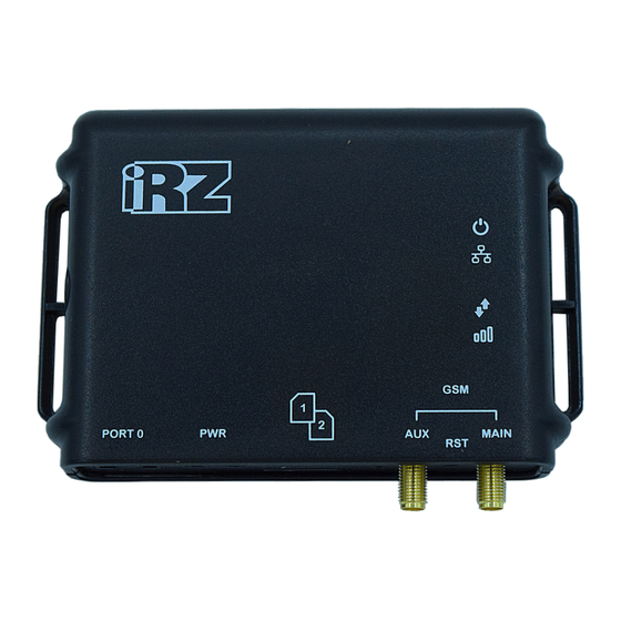
Figure 1. Front View (RL01, RU01)
Figure 2. Top View
Interfaces
Table 3.1 Power Connector Pin Assignment
Figure 3. Power Connector
Table 3.2 Ethernet Connector Pin Assignment
Figure 4. Ethernet Connector
Router Indication
Table 3.3 Connector Assignment
Table 3.4 Router Indication
Settings Access
4 Contacts and Support
Advertisement
Quick Links
Download this manual
USER GUIDE
iRZ GSM/3G/LTE Routers:
RL01, RU01
Table of
Contents
Previous
Page
Next
Page
1
2
3
4
5
Advertisement
Table of Contents
Need help?
Do you have a question about the RL01 and is the answer not in the manual?
Ask a question
Questions and answers
Related Manuals for iRZ RL01
Network Router iRZ RUH2 User Manual
Gsm router irz ruh2 3g hsupa/hsdpa/umts/edge/gprs (56 pages)
Network Router iRZ ruh2b User Manual
(31 pages)
Network Router iRZ RCA CDMA 450 User Manual
Gsm router (55 pages)
Network Router iRZ RU41 User Manual
Gsm/3g/cdma/lte routers (22 pages)
Network Router iRZ RL41 User Manual
Gsm/3g/cdma/lte routers (22 pages)
Network Router iRZ RL41l User Manual
Gsm/3g/cdma/lte routers (22 pages)
Network Router iRZ RL01w User Manual
Gsm/3g/lte routers (15 pages)
Network Router iRZ RU01w User Manual
Gsm/3g/lte routers (15 pages)
Network Router iRZ RU01 User Manual
Gsm/3g/lte routers (15 pages)
Network Router iRZ RU21w User Manual
Gsm/3g/lte-routers (21 pages)
Network Router iRZ RL21w User Manual
Gsm/3g/lte-routers (21 pages)
Network Router iRZ RU22w User Manual
Gsm/3g/lte-routers (21 pages)
Network Router iRZ RL22w User Manual
Gsm/3g/lte-routers (21 pages)
This manual is also suitable for:
Ru01
Table of Contents
Print
Rename the bookmark
Delete bookmark?
Delete from my manuals?
Login
Sign In
OR
Sign in with Facebook
Sign in with Google
Upload manual
Upload from disk
Upload from URL


Need help?
Do you have a question about the RL01 and is the answer not in the manual?
Questions and answers