Table of Contents
Advertisement
Available languages
Available languages
Quick Links
READ THESE INSTRUCTIONS AND
SAVE THEM FOR FUTURE USE
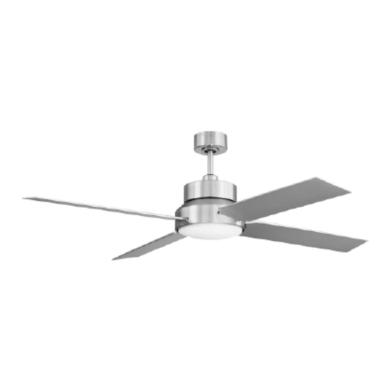
Dialogue
Installation Guide
Table of Contents:
Safety Tips. pg. 1
Unpacking Your Fan. pg. 2
Parts Inventory. pg. 2
Installation Preparation. pg. 3
Hanging Bracket Installation. pg. 3
Fan Assembly. pgs. 4 - 5
Wiring. pg. 5
Canopy Assembly. pg. 6
Blade Assembly. pg. 6
Remote Control Operation. pg. 9
Testing Your Fan. pg. 9
Troubleshooting. pg. 10
Warranty. pg. 10
Parts Replacement. pg. 10
E192641
net weight of fan: 23.57 lb. (10.69 kg)
PRINTED IN CHINA
Advertisement
Table of Contents

Subscribe to Our Youtube Channel
Related Manuals for stori Dialogue

Summary of Contents for stori Dialogue
-
Page 1: Table Of Contents
READ THESE INSTRUCTIONS AND SAVE THEM FOR FUTURE USE Dialogue Installation Guide Table of Contents: Safety Tips. pg. 1 Unpacking Your Fan. pg. 2 Parts Inventory. pg. 2 Installation Preparation. pg. 3 Hanging Bracket Installation. pg. 3 Fan Assembly. pgs. 4 - 5 Wiring. -
Page 2: Safety Tips
SAFETY TIPS. WARNING: To reduce the risk of electrical shock, turn off the electricity to the fan at the main fuse box or circuit panel before you begin the fan installation or before servicing the fan or installing accessories. READ ALL INSTRUCTIONS AND SAFETY INFORMATION CAREFULLY BEFORE INSTALLING YOUR FAN AND SAVE THESE INSTRUCTIONS. -
Page 3: Unpacking Your Fan
1. Unpacking Your Fan. Carefully open the packaging. Remove items from Styrofoam inserts. Remove motor housing and place on carpet or Styrofoam to avoid damage to finish. Do not discard fan carton or Styrofoam inserts should this fan need to be returned for repairs. -
Page 4: Installation Preparation
3. Installation Preparation. blade edge To prevent personal injury and damage, ensure that the hanging location allows the blades a inches clearance of 7ft. (2.13m) from the floor and 30in. 7 feet (76cm) (76cm) from any wall or obstruction. (2.13m) This fan is suitable for room sizes up to 400 square feet (37.2 square meters). -
Page 5: Fan Assembly. Pgs
5. Fan Assembly. If you wish to extend the hanging length of your fan, set screw hole you must remove the hanging ball from the downrod set screw provided to use with an extended downrod (sold stop pin separately). [If you wish to use the downrod provided, please proceed to instructions following the dotted line below.] To remove hanging ball, loosen set screw on hanging... -
Page 6: Wiring
5. Fan Assembly. (cont.) wood safety cable loop ceiling joist With the hanging bracket secured to the outlet box and able to support the fan, you are now ready to hang your fan. Grab the fan firmly with two hands. Slide downrod wood screw through opening in hanging bracket and let hanging and washer... -
Page 7: Canopy Assembly
7. Canopy Assembly. antenna Locate 2 screws on underside of hanging bracket receiver and remove screw closest to the open end of the hanging hanging bracket. Partially loosen the other screw. Lift bracket canopy to hanging bracket. Place rounded part of slotted hole in canopy over loosened screw in screw hanging bracket and push up. - Page 8 9. Light Kit Assembly (Optional). (cont.) Remove 1 screw from post on underside of fitter plate and partially loosen the other 2 screws. motor housing Connect WHITE wire from motor housing to WHITE wire from LED light kit. Connect BLACK (or BLUE) wire from motor housing to BLACK wire from LED light kit.
-
Page 9: Automated Learning Process./ Activating Code
10. Automated Learning Process./ Activating Code. CAUTION: The remote control transmitter can be remote control programmed to multiple receivers or fans. If this is transmitter (backside) not desired, turn wall switch off to any other programmable receiver or fan. Remove battery cover from backside of remote control transmitter. -
Page 10: Remote Control Operation
11. Remote Control Operation. to control fan speed button - turns fan to HIGH speed button - turns fan to MEDIUM speed button - turns fan to LOW speed button - turns fan OFF to control light brightness - turns light kit ON/OFF when pressed once; dims light kit when pressed and held down 12. -
Page 11: Troubleshooting
Troubleshooting. Warranty. WARNING: Failure to disconnect power supply STORIMODERN LIFETIME LIMITED WARRANTY: STORIMODERN warrants this fan to the original household prior to troubleshooting any wiring issues may purchaser for indoor/outdoor use under the following result in serious injury. provisions: 1-YEAR WARRANTY: STORIMODERN will replace or repair Problem: Fan fails to operate. - Page 12 LEER ESTAS INSTRUCCIONES Y GUARDARLAS PARA UTILIZACION FUTURA Dialogue Guía de instalación Índice de materias: Sugerencias de seguridad. Pág. 1 Desempaquetado del ventilador. Pág. 2 Inventario de piezas. Pág. 2 Preparación para la instalación. Pág. 3 Instalación del soporte de montaje. Pág. 3 Ensamblaje del ventilador.
- Page 13 SUGERENCIAS DE SEGURIDAD. ADVERTENCIA: Para evitar la posibilidad de una descarga eléctrica, desconectar la corriente en la caja de fusibles principal o el interruptor protector antes de iniciar la instalación del ventilador o antes de repararlo o instalar accesorios. LEER TODAS LAS INSTRUCCIONES E INFORMACIÓN DE SEGURIDAD CUIDADOSAMENTE ANTES DE INSTALAR SU VENTILADOR Y GUARDAR ESTAS INSTRUCCIONES.
- Page 14 1. Desempaquetado del ventilador. Abrir el empaque cuidadosamente. Sacar los artículos del embalaje. Sacar el motor y ponerlo en una alfombra o en el embalaje para evitar rayar el acabado. Guardar la caja de cartón o el empaquetamiento original en caso de que tenga que mandar el ventilador para alguna reparación.
- Page 15 borde 3. Preparación para la instalación. del aspa 76cm Para prevenir daño corporal y otros daños, estar seguro de que el lugar en donde va a colgar el ventilador le 2,13m pulg.) permite un espacio libre de 2,13 m (7 pies) entre las (7 pies) puntas de las aspas y el piso y 76 cm (30 pulg.) entre las aspas y cualquier pared u otra obstrucción.
- Page 16 5. Ensamblaje del ventilador. agujero para Si usted desea extender la longitud colgante del el tornillo ventilador, usted tendrá que quitar la bola que sirve tornillo de fijación para colgar del tubo provisto para usarla con un tubo de fijación más largo (a la venta por separado).
- Page 17 viga de bucle del cable 5. Ensamblaje del ventilador. (cont.) madera de seguridad Ya que esté sujetado el soporte de montaje a la caja de salida y capaz de apoyar el ventilador, usted está listo para colgar el ventilador. Agarrar el ventilador firmemente con las dos manos. tornillo para Deslizar el tubo por la abertura del soporte de montaje y dejar que madera...
- Page 18 7. Colocación de la cubierta decorativa. antena Localizar los 2 tornillos en la parte inferior del soporte de receptor montaje y quitar el tornillo que está localizado más cerca del extremo abierto del soporte de montaje. Aflojar parcialmente el soporte de otro tornillo.
- Page 19 9. Instalación del juego de luz (opcional). (cont.) Quitar 1 tornillo del poste que se encuentra en la parte inferior de la placa de conexión y parcialmente aflojar los otros 2 tornillos. bastidor Conectar el cable BLANCO del bastidor del motor al del motor cable BLANCO del juego de luz LED.
- Page 20 10. Proceso de aprendizaje automático./El activar el código. PRECAUCIÓN: Se puede programar el transmisor del control remoto para usar con varios receptores o ventiladores. Si no desea hacer esto, apagar el interruptor de cualquier otro receptor o ventilador transmisor del control remoto programable.
- Page 21 11. Funcionamiento del control remoto. para controlar la velocidad del ventilador botón - pone el ventilador en velocidad ALTA botón - pone el ventilador en velocidad MEDIA botón - pone el ventilador en velocidad BAJA botón - APAGA el ventilador para controlar el brillo de la luz - ENCIENDE/APAGA el juego de luz cuando se oprime el botón una vez;...
- Page 22 Localización de fallas. Garantía. ADVERTENCIA: El no desconectar el suministro de GARANTIA LIMITADA DE POR VIDA DE STORIMODERN: STORIMODERN garantiza este ventilador al comprador fuerza eléctrica antes de hacer localización de fallas original de grupo familiar para uso interior/al aire libre con para cualquier problema de instalación eléctrica puede las siguientes condiciones: causar lesiones graves.
Need help?
Do you have a question about the Dialogue and is the answer not in the manual?
Questions and answers