
Subscribe to Our Youtube Channel
Related Manuals for SolarEdge Gamatronic B120US


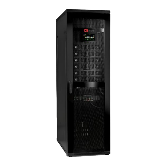
Summary of Contents for SolarEdge Gamatronic B120US
- Page 1 This installation guide is for product #101SW466. AMATRONIC HREE HASE ODULAR 208V FOR THE GRID B120US INSTALLATION GUIDE Revision 3.0, January 2020 (Doc. 2MUM-B120I)
- Page 2 Remember to register your product at: http://www.gamatronic.com/product-warranty in order to activate your warranty. UPS for 208 Vac Grid, B120US Installation Guide, doc. rel. 3.0...
- Page 3 TANDARDS AND ONVENTIONS This user manual contains diagrams which include images of the display screen of the UPS. Unless otherwise indicated, the readings shown in the screen images are only illustrative, and are not intended to match the readings on a specific system in any particular environment. Operation and control of the UPS is accomplished through a touch-sensitive LCD display screen.
-
Page 4: Table Of Contents
TABLE OF CONTENTS UNPACKING INSTRUCTIONS ..........................1 SAFETY PRECAUTIONS ............................5 2.1. ’ ................................. 5 2.2. ’ ................................7 SYSTEM STRUCTURE AND INSTALLATION ......................8 3.1....................... 12 MPORTANT NSTALLATION NFORMATION 3.2............................. 13 NSTALLATION HECKLIST 3.3........................... 21 NSTALLATION ROCEDURE Visual Inspection .......................... - Page 5 PROCEDURE: MAINTENANCE BYPASS MODE ....................83 7.1............................ 84 IRCUIT REAKER AYOUT 7.2............84 RANSFERRING THE TO MAINTENANCE YPASS MODE FROM NORMAL MODE 7.3............ 87 RANSFERRING THE BACK TO NORMAL MODE FROM MAINTENANCE BYPASS MODE USING THE UPS WITH A GENERATOR ......................89 8.1.
- Page 6 LIST OF FIGURES 1: I ....................1 IGURE NSPECT THE SHIPPING CRATE FOR SIGNS OF DAMAGE 2: S ........................2 IGURE HOCK ATCH AND ATCH DEVICES 3: R ) ................3 IGURE EMOVE THE ROOF AND SUPPORT BEAMS USE ELECTRIC SCREWDRIVER 4: R ..........................
- Page 7 46: LVD ............................68 IGURE WIRING DIAGRAM 62: A UPS' ............................. 69 IGURE S BYPASS CIRCUIT 63: T ) ..................72 IGURE TATIC WITCH IN CONTEXT STAND ALONE SYSTEM 50: P 9) ....................... 73 IGURE ARALLEL COMM CONNECTIONS ABLE 51: L ............
- Page 8 LIST OF TABLES 1: K 5 ..............................9 ABLE EY TO IGURE 2: K 6 ..............................11 ABLE EY TO IGURE 3: R ........................... 24 ABLE ECOMMENDED CLEARANCES 4: R 20-120 UPS ..........30 ABLE ECOMMENDED CIRCUIT BREAKERS FOR THE CURRENT RATING FOR 5: B ...............
-
Page 9: Unpacking Instructions
1. Unpacking Instructions 1. Inspect the shipping crate for any signs of damage that may have occurred while in transit. Figure 1: Inspect the shipping crate for signs of damage 2. Inspect the ShockWatch and TiltWatch devices, which are adhered to the outside of the wooden packing crate. -
Page 10: Figure 2: Shockwatch And Tiltwatch Devices
- OR - Figure 2: ShockWatch and TiltWatch devices These devices indicate if the package was subject to shock or tip-over. 4. Using a forklift, move the shipping crate close to the place in which the UPS will be installed. 5. -
Page 11: Figure 3: Remove The Roof And Support Beams (Use Electric Screwdriver)
Figure 3: Remove the roof and support beams (use electric screwdriver) 7. Remove the screws that are holding the walls and support beams of the crate in place. Then carefully remove the walls themselves leaving the UPS standing on its wooden shipping pallet. - Page 12 Be careful to avoid scratching the finish of the Modular UPS. 10. Lift the UPS from the shipping pallet and move it to the location where it will be installed. UPS for 208 Vac Grid, B120US Installation Guide, doc. rel. 3.0...
-
Page 13: Safety Precautions
2. Safety Precautions The UPS system is designed for a wide range of environments. Nevertheless, the modular UPS should be handled with care, according to the following guidelines. 2.1. Do’s Read this manual and the User Guide carefully before starting installation and operation of the ... - Page 14 If you remove a power module from the UPS while the module is operating, wait five minutes before reinserting the module. This allows the module’s capacitors time to discharge. FAST FUSES (SEMICONDUCTOR FUSES) must be used between the battery and the UPS – for ...
-
Page 15: Don'ts
2.2. Don’ts Do not open the cover of the UPS or the battery cabinets under any circumstances. All UPS panels and doors should be closed. Do not insert any objects through the ventilation holes. Do not put objects on the UPS. ... -
Page 16: System Structure And Installation
3. System Structure and Installation The UPS is composed of: Up to 6 power modules, each providing 20 kVA/18 kW Static switch module System controller Maximum output capacity of the UPS is 120 kVA/108 kW. Figure 5: Major UPS components (front view) UPS for 208 Vac Grid, B120US Installation Guide, doc. - Page 17 Table 1: Key to Figure 5 Item Description The system controller and the LCD screen combined. The UPS cabinet’s front door Power modules. Each supplies 20 kVA / 18 kW. Removable Static Switch and 5 dry contacts. “Connector group 1”. Dry contacts and communication connections.
-
Page 18: Figure 6: Main Terminals Viewed From The Ups Rear
Figure 6: Main terminals viewed from the UPS rear UPS for 208 Vac Grid, B120US Installation Guide, doc. rel. 3.0... -
Page 19: Table 2: Key To Figure 6
Table 2: Key to Figure 6 Item Description Bypass Input (L1) Bypass Input (L2) Bypass Input (L3) Ac Input (L1) Ac Input (L2) Ac Input (L3) Ac Output (L1) Ac Output (L2) Ac Output (L3) Positive battery terminal (+) Battery midpoint and Neutral bus bar. Negative battery terminal (–) Protective earth (ground) bus bar LL POWER CONNECTIONS MUST BE COMPLETED BY A LICENSED... -
Page 20: Important Installation Information
3.1. Important Installation Information The Gamatronic UPS must be connected a “4-wire + Ground” configuration (i.e., 3 phases + Neutral + Ground). The voltage displayed on the status screen is the Phase-to-Neutral voltage. The Neutral line MUST be connected to the UPS on the input and output stages of the UPS. The UPS will support phase-to-phase loads and phase-to-Neutral loads. -
Page 21: Installation Checklist
3.2. Installation Checklist Complete the following checklist as you perform the installation, initialization, configuration, and testing procedures. Refer to the appropriate sections (specified in the Reference column) for detailed information about each checklist item. The detailed explanation of each section can be found in Section ... - Page 22 Mechanical Test One by one, place each power module in a shelf and push it all the way in. Verify that each module makes a mechanincal connection with the power backplane on the inside rear of the shelf. Slide out each Power module by about 3 inches, enough to unplug them from the power backplane, and attach the right and left ribbon cables between the modules and the base.
- Page 23 Measure dc voltage at battery cabinet switch, +200 V and –200 V (±8 %) in reference to midpoint, and verify polarity. Ground, input neutral, rectifier Connect ground, neutral, rectfier ac input, and bypass inputs, and output 3 .3.3 bypass ac input, and ac output cables to the UPS acording to Figure 9 and Figure 10.
- Page 24 System Start-Up Remove all power modules, switch ON bypass and rectifier input circuit breakers and keep the output breaker OFF. The system controller and Static Switch will switch ON. LCD screen and system output are on. Note: the Static Switch will supply output power from the bypass.
- Page 25 Module start up process First time module installation: 1. Turn off the bypass and rectifier input circuit breaker. Then insert a single power module and connect the right and left flat cables. If the bypass and input are bridged, slide out the Static Switch at least 5 inches.
- Page 26 √ Check DC voltage Turn on the battery circuit breakers and wait for the dc realys to connect the rectifer to the battery. If the battery voltage is low verify that the battery is charging and wait until the battery reaches its floating voltage.
- Page 27 Check OUTPUT values Verify that the system is on inverter, if not transfer load to the inverter "Main>Operation>Transfer load>Transfer load to inverter" Preform a complete shutdown to all but one power module. "Main>Operation>on/off>modules off>complete shutdown" Ac output phase-to-neutral voltages (should be 120 V, ±2%). L1 –...
- Page 28 Confirm that there are no system alarms. Battery test: preform a battey test main>operation> battery test. The batteries are required to hold the inverter DC voltage and pass until the end of the 5 minutes. Self-Load test: During system commissioning, the charger, battery, inverter and bypass of the UPS module shall be tested at full load without the need for an external load bank.
-
Page 29: Installation Procedure
Connect the Ethernet cable. Configures IP address, time server, and DHCP, according to the preferences of the local IT team. (“Main > Setup > Communications”) Export the log and then clear the log. 3.3. Installation Procedure After completing each step in the following installation, return to the Installation Checklist (Section ... - Page 30 To perform physical site preparation: 1. Ensure that the ambient temperature in the immediate vicinity of the UPS complies with system requirements: Minimum/maximum operating temperatures: +14°F / +104 °F (–10 °C / +40 °C). Recommended operating temperature: Between +59°F and +77 °F (+15°C and +25 °C). ...
-
Page 31: Figure 7: Dimensions Of The Gamatronic Ups
Figure 7: Dimensions of the Gamatronic UPS UPS for 208 Vac Grid, B120US Installation Guide, doc. rel. 3.0... -
Page 32: Electrical Site Preparation
Table 3: Recommended clearances ECOMMENDED MINIMUM CLEARANCE AROUND THE Front 110 cm (43 in.) Minimum adequate clearance for user access and service. Rear 100 cm (39 in.) Minimum adequate clearance for cable connections. No minimum clearance, provided that the UPS is not placed next to heat-emitting or electronic equipment. -
Page 33: Cabling
3. Verify that the input and output power cable connections, ground, and neutral lines comply with local and national codes and are appropriate for the circuit breakers protecting them. 4. Measure the ac input voltage. Phase-to-phase voltage (measured between L1-L2, L2-L3, and L3-L1) should be 208 Vac ±10 %. -
Page 34: The Neutral Line
The Neutral Line 3.3.4.2. When the UPS is operating, a neutral line must be connected at all times and must not be disconnected at any time. Caution: If at any time the neutral line becomes disconnected, there will be no input or output reference voltage because the input neutral line and the output neutral line are physically linked together. -
Page 35: Figure 9: Recommended System Connections
Figure 9: Recommended system connections Note: For recommended circuit breaker and fuse ratings, see Table 4. UPS for 208 Vac Grid, B120US Installation Guide, doc. rel. 3.0... -
Page 36: Figure 10: Recommended Connections With Input Isolation Transformer
Figure 10: Recommended connections with input isolation transformer Note: For recommended circuit breaker and fuse ratings, see Table 4. UPS for 208 Vac Grid, B120US Installation Guide, doc. rel. 3.0... -
Page 37: Figure 11: Terminal Connections
Figure 11: Terminal connections Access to the main terminals on the B120US can be obtained by simply opening the back door of the UPS. To the electrical panel to which the UPS is connected, affix a sign or label with the following warning: WARNING: There is a UPS attached to this electrical panel. -
Page 38: Connecting The Ups To The Electrical Panel
Connecting the UPS to the electrical panel 3.3.4.4. When connecting the electrical panel to The Gamatronic UPS, a torque of 10 to 20 Nm is recommended on the UPS terminal side. The lug size needed to fit a 3/8" or metric M10 screw size. -
Page 39: Assembling And Connecting External Batteries
Annotations For installation: (*) Without installation transformer. (**) With isolation transformer only. IMPORTANT: If local electrical codes are stricter than the above recommendations, the local codes take priority. Assembling and connecting external batteries 3.3.4.5. The UPS supports the use of standard lead-acid batteries, and also lithium- ion batteries. -
Page 40: Figure 12: Connecting A Single Battery Set
to the output capacity of the UPS. Figure 12 assumes that the battery fuses can be easily disconnected, when used in series with a battery circuit breaker, as desired. 4. Measure the dc voltage at the main terminals of the battery cabinets. Verify that you obtain values of at least 192 Vdc for each battery cabinet, or at least 384 Vdc across the main battery CB. -
Page 41: Figure 13: Connecting Multiple Battery Sets, Using Cbs
Current values are for fuses F1 through F4 in Figure 20 and are based on 10- minute backup time at full load. If longer backup time is required, please consult with Gamatronic Support. Figure 13: Connecting multiple battery sets, using CBs Figure 13 shows how two battery sets can be connected to the UPS. -
Page 42: Table 6: Battery Lifetime Vs Environmental Temp. (Illustrative, As Per Eurobat)
Table 6: Battery lifetime vs environmental temp. (illustrative, as per Eurobat) NVIRONMENTAL CHIEVABLE PERCENTAGE OF BATTERY S RATED LIFETIME TEMPERATURE 20 °C 100 % 30 °C 50 % 40 °C 25 % UPS for 208 Vac Grid, B120US Installation Guide, doc. rel. 3.0... -
Page 43: Powering Up The System
Powering up the system 3.3.5. This section represents the UPS system state as it unboxed with initial Factory Settings. To power up the system: Initial configuration consists of three stages: 1. Before powering the UPS 2. Execution of the system startup wizard 3. -
Page 44: Figure 14: Initial Configuration Wizard
When the UPS is initially started up, a series of configuration screens are presented on the LCD display panel. You will be prompted to provide the UPS with basic system configuration information in order to enable initial operation of the UPS. To perform initial UPS configuration: 1. -
Page 45: Figure 15: Initial Configuration Wizard: Password Entry
The Password screen appears: Figure 15: Initial configuration wizard: password entry 3. Type the Technician password you received form Gamatronic in the Password text input field and press OK. Without a password you cannot continue. The Battery Capacity screen appears: Figure 16: Initial configuration wizard: battery capacity in Ah The capacity is used by the UPS when it is in battery mode in order to calculate the amount of backup time remaining. -
Page 46: Figure 17: Initial Configuration Wizard: Set Time Zone
If you are not sure of your batteries’ Ah capacity, check one of the batteries in the battery cabinet(s). The Ah rating is usually indicated on the battery's exterior. The Ah rating of a single battery is the same as for the entire cabinet. When using multiple battery banks the Ah value of each battery bank must be added (i.e. -
Page 47: Figure 18: Exit Configuration Wizard
The Finish screen appears: Figure 18: Exit configuration wizard 6. Select Finish. The initialization menu wizard exits. 7. Continue the first time installation process (See Section 3 .3.6.2). UPS for 208 Vac Grid, B120US Installation Guide, doc. rel. 3.0... -
Page 48: Continuing First Time Startup Process
Continuing first time startup process 3.3.6.2. To continue the first time startup process: 1. If you are using lithium-ion batteries, contact Gamatronic support for configuration instructions and check the values in the Setup > Battery parameters against the information in the battery manufacturer’s data sheet. Verify that the parameter values are appropriate for the batteries you have chosen. - Page 49 If the power module was shut down during factory quality testing you will have to manually turn on the module. System Menu > Operation > On/off > Modules on The Modules on screen appears: Press Confirm. 6. Select and shut down the module. (System Menu >...
- Page 50 9. Insert the next power module 3/4 of the way in and attach the 2 flat cables then, slide it in fully. 10. Turn on the power module (Main > Operation > Turn On/Off > Modules on). The Modules on screen appears: 11.
-
Page 51: Figure 21: Confirm Disconnecting The Load
Figure 21: Confirm Disconnecting the Load 17. Confirm OK. 18. Turn off all input circuit breakers. 19. If removed previously, insert the Static Switch. 20. Turn on bypass, rectifier and battery circuit breakers 21. Turn on the system. (Main > Operation > On/Off > System on) The Confirm Turn System On screen appears: Figure 22: Confirm Switch on All Modules 22. -
Page 52: Figure 23: The Alarms Icon Indicates Alarm Conditions
For additional information about responding to Alarm indications, refer to the Troubleshooting Guide. Figure 23: The Alarms icon indicates alarm conditions 28. Perform a brief battery test to verify that the UPS is ready and able to operate in battery mode when it is needed (Operation >... -
Page 53: Figure 25: Battery Test In Progress Screen
Figure 25: Battery Test in Progress screen After 5 minutes verify that the battery test has passed. 30. Verify that the ac output circuit breakers on the electrical panel are OFF, and verify proper phase rotation over all CBs. 31. On the Status screen, verify that the bypass and the inverters are synchronized. This is the recommended stage at which to perform load testing, before transferring the customers critical load to being supported by the UPS. - Page 54 34. You can now connect a load device to the ac output circuit breaker and then turn ON the ac output circuit breakers on the electrical panel. 35. If working with operating loads turn off the maintenance bypass circuit breaker to move the load to the UPS.
- Page 55 The Set Last Maintenance Date screen appears: Figure 28: Set Last Maintenance Date screen 3. Set the correct last maintenance date using the Day, Month, Year sliders. This will set a system maintenance reminder alarm one year from the current date. 4.
-
Page 56: Assigning Ip Address To The Ups
Assigning IP Address to the UPS 3.3.6.3. This procedure assigns an IP address to the UPS. Assigning an IP address allows you to remotely monitor the UPS over an IP network. If you do not want to remotely monitor the UPS, you can skip this step. If you decide to later implement remote monitoring, you can perform this process at that time. - Page 57 The IP Address, Subnet Mask, and Default Gateway text input fields are automatically populated. 3. Click Confirm. The UPS software has obtained an IP address. To assign an IP address manually: 1. From the System Menu select Setup > Connectivity > IP Address Configuration. 2.
-
Page 58: Testing
To select an address field on the screen, tap the field with your finger. Depending on the particular model of screen on your system, dragging your finger lightly across the field from right to left may yield best results. 4. When you have completed entering all of the addresses, select Confirm. The addresses you entered are saved to the UPS system controller. -
Page 59: Figure 31: Enable Pq Mode
1. Enable PQ mode (System Menu > Setup > System > System type > PQ mode). The PQ Mode screen appears: Figure 32: Enable PQ Mode 2. Select Enable and then select Confirm. 3. PQ Mode is enabled. 4. Transfer system from VF mode to PQ mode with 2 kW active load (System Menu > Operation >... - Page 60 The UPS On – PQ Output status screen appears: Figure 34: PQ Mode 10. Verify that the Rectifier Input current level has gone up and the Static switch is bridged to the inverter (See Figure 34). 11. Navigate back to the PQ Mode setup screen, and change PQ power, by increasing the active power in 10% increments.
-
Page 61: Test: Under Load
Figure 35: Reactive load testing 14. Run for 5-10 min on each iteration. 15. When you have completed system acceptance testing lower the active and reactive load levels in 10% increments back down to 0 using the Active power slider and Reactive power slider. -
Page 62: Test: Battery And Blackout Mode
1. Turn off all ac and dc CBs and isolate the system. 2. Connect an average or standard load to the system. 3. Turn on ac input CBs and measure the ac input voltage during operation under load. Take the measurements at the output terminals of UPS (phase-to-phase between L1-L2, L2-L3, and L3-L1 and phase-to-neutral at L1, L2, and L3). -
Page 63: Figure 36: Generator Mode
The rectifier will then begin its power walk-in to slowly transfer the load from the battery to the generator. An auxiliary contact can be set to limit battery charging during the use of the generator. Select an auxiliary contact that can be wired to the N.O. (normally open) (default system controller set) or N.C. -
Page 64: Test: Eco Mode
The Input Dry Contacts screen appears: Figure 38: Changing the auxiliary contact to normally closed 2. In the Input Dry Contacts screen, locate the Generator dry contact now that you have enabled it, and select normally open or normally closed depending on your ATS or Generator’s auxiliary output. -
Page 65: Figure 38: Eco Mode Screen - Enabled Checkbox
To put the system in ECO Mode: In order to unlock ECO Mode you require a special code from Gamatronic support. 1. Switch to Technician level user. 2. From the System Menu navigate to Setup > System > System Type > ECO Mode. The Password screen appears. -
Page 66: Figure 39: Turning On Eco Mode
The Operation screen appears: Figure 40: Turning on ECO Mode 7. Select ECO Mode off (click for change). The ECO Mode off button is toggled on. The next step is to confirm ECO Mode is active. 8. From the System Menu go to Status. The Status screen appears: Figure 41: Status screen, UPS ON and ECO Mode ON Notice the Status screen indicates UPS ON and ECO Mode message. -
Page 67: Test: Ip Communication With Controller
The system will run on ECO mode until either there is a variant in the grid power supply or the system is manually transferred back to normal mode. You have successfully 1) enabled ECO Mode, and 2) turned ECO Mode on. Test: IP Communication with Controller 3.4.6. -
Page 68: Figure 41: Web View
The UPS System Menu should appear: Figure 42: Web View This confirms IP communication with the controller. UPS for 208 Vac Grid, B120US Installation Guide, doc. rel. 3.0... -
Page 69: Auxiliary Connections
4. Auxiliary Connections Besides the main power terminals, the UPS has a number of auxiliary connections. They are grouped together on the front panel of the UPS in what is referred to as connector group 1, and connector group 2. (See Figure 43). Figure 43: Location of Connector Groups 1 and 2 on the front of the UPS Location of connector groups 1 and 2 is shown in Figure 43, and close-up views of the connectors are shown further on in the text where relevant. - Page 70 Figure 44: Close-up of Connector Group 1 Table 7: Key to Figure 44 ESCRIPTION P23 Load-on-bypass dry contact, N.O. Forced Bypass contacts. N.O. When these contacts are closed, the UPS immediately goes into Bypass mode. These contacts are intended to be used in conjunction with the Maintenance Bypass function.
-
Page 71: Table 8: Description Of Connector Group 2 (Key To Figure 44)
Figure 45: Connector group 2 Table 8: Description of Connector Group 2 (Key to Figure 45) ONNECTION OMMENT NAME Digital output #1 Low Battery Digital output #2 AC fail LVD (this works in tandem with P13 pins 1 and 3) Digital output #3 Do NOT remove P2 or P13 Digital output #4... - Page 72 RS485 Parallel A RS485 Parallel B Temp. sensor #1 A Temp. sensor #1 B Temp. sensor #2 A Temp. sensor #2 B Digital input #1 Common Digital input #2 (Optional: Generator mode) Common Digital input #3 Surge protector fault Common Digital input #4 (Optional: Maintenance bypass) Common...
- Page 73 Battery current #1 -12 V +12 V Battery current #1 Do NOT remove -12 V +12 V Battery current #1 -12 V +12 V Battery current #1 Negative Battery Current -12 V Digital output #2 Common Digital output #1 Remote panel PWR Remote panel DAT Remote panel CLK Remote panel Gnd...
-
Page 74: Input And Output Dry Contacts
4.1. Input and Output Dry Contacts The UPS has input and output dry contacts. The input dry contacts enable the UPS’s computer to monitor the state (open or closed) of a relay external to the UPS, and to generate an alarm if the state of the external relay changes. The output dry contacts enable the UPS to trigger an external circuit in response to a system alarm. -
Page 75: Surge Protector Malfunction Alarm
To restart the UPS after EPO: 5. Reset the EPO switch. 6. Switch OFF all of the following circuit breakers: ac input, bypass ac input, battery. 7. Wait 1 minute. 8. Switch on the ac input circuit breaker and the bypass input circuit breaker 9. -
Page 76: Figure 46: Lvd Wiring Diagram
Figure 47: LVD wiring diagram Figure 47 shows how to wire UPS to enable the LVD battery protector. Wire should be 12AWG or of a cross-section area 2.5 mm is recommended. For additional information about configuring the LVD function, refer to the UPS User Guide. -
Page 77: Circuit Breaker Selectivity
5. Circuit Breaker Selectivity When discussing power distribution, “selectivity " (also referred to as “discrimination”), it is the selection and arrangement of circuit breakers such that in the event of a short circuit or overload in the line, the circuit breaker closest to the short will be tripped and the upstream circuit breakers remain unaffected. - Page 78 as when a load with high-inrush current is turned on. In such a case you would only want the circuit breaker to trip if the current overload continued for an abnormal length of time. Using Figure 48 as an example, optimal discrimination of circuit breakers in series can be achieved by choosing them in such a way that when a short circuit occurs, the response of circuit breaker feeding the bypass line (CB01) line will be based on thermal (slower-acting) tripping, while the circuit breaker closest to the short circuit (CB05) will respond based on magnetic (instantaneous)
-
Page 79: Parallel Operation
6. Parallel Operation 6.1. Theory When two or more UPS units are deployed in parallel, they are connected according to the decentralized Static Switch method (see below). Special technical solutions and control algorithms are implemented to synchronize all units in the system to prevent circulation of energy between them and to isolate a faulty unit from the common power bus. -
Page 80: Parallel Communication
Figure 49: The Static Switch in context (stand-alone system) When two or more UPSs are configured in parallel mode, the Static Switches are synchronized by dedicated control communication to ensure that if one unit goes to Bypass mode, the rest of the units will also transfer to Bypass mode simultaneously. -
Page 81: Figure 50: Parallel Comm
Figure 50: Parallel comm. connections (see Table 9) Figure 51: Location of the parallel comm. connections at inside-rear of the system Connections for the two parallel communication cables when two or more UPS’s are being operated in parallel configuration. All parallel communication cables (the 25-pin cables) must be housed in appropriate conduits. -
Page 82: Epo And Parallel Operation
EPO and parallel operation 6.1.2.1. An EPO switch can also be used if you intend to operate multiple UPS units in parallel. An external n-pole / N.O. EPO switch may be connected according to the connection schematic. EPO disconnection of the parallel units MUST BE SIMULTANEOUS! EPO wiring and switch rating must be 5 A / 120 Vac. -
Page 83: Table 9: Cable Sets For Parallel Communication Between Upss
When reading this section, refer also to the appropriate connection diagram: Figure 57, depending on the number of UPSs to be connected in parallel. To setup UPSs in parallel mode: 1. The UPS units should be located near to one another. They must be connected to one another in a ring configuration using the parallel communication cables. -
Page 84: Figure 52: Common Dc Parallel Communication Cable
Figure 52: Common DC Parallel communication cable Figure 53: Decentralized DC Parallel communication cable 4. Verify that each UPS’s output circuit breaker is in the OFF position (CB5 in the connection diagrams - Figure 57). 5. Turn on one of the systems. This system will become the “master” system. Wait until the startup procedure is complete –... - Page 85 Figure 54: The System Menu screen The screen should display UPS ON, Normal mode message, and there should be no alarms present. If there are active alarms, resolve any problems before continuing. 6. Put the UPS in multisystem mode (System Menu > Setup > System > Multisystem mode).
- Page 86 Figure 55: The crown icon indicates the Master Power Module A crown shaped icon appears on the Master Power Module. From the System Menu go to Status > Modules to view it. Only one power module within the set of power modules is designated Master Power Module.
- Page 87 Figure 56: Ac output voltage display for a single module 11. You will see the ac output voltage display, per module. By tapping on each of the module icons on the left side of the screen you can see which modules have an output voltage that is more than 2 % different from the Master system.
- Page 88 17. Compare the output current from each pair of systems. Under full load, the difference in output current between any two systems should not exceed ±10 % of the total system output current. 18. The parallel systems are now ready for use for any loads up to the maximum rated output in kW of the combined systems.
- Page 89 Figure 58: Connection diagram for 4 Units in Parallel UPS for 208 Vac Grid, B120US Installation Guide, doc. rel. 3.0...
-
Page 90: Maintenance Bypass For Parallel Systems
Maintenance bypass for parallel systems 6.2.1. A maintenance bypass switch can be installed to enable a technician to perform maintenance work on the parallel UPSs without impacting the supply of power to the loads. The maintenance bypass switch routes the current around the UPSs, for the safety of the technician. The optional maintenance bypass switch is shown in the connection schematics for parallel systems (Figure 58). -
Page 91: Procedure: Maintenance Bypass Mode
7. Procedure: Maintenance Bypass Mode In maintenance Bypass mode, the UPS does not to supply power to the load and the UPS is isolated from the mains power. This enables a technician, after turning off ALL the input, output and battery circuit breakers, to work safely on the UPS. The technician can perform full maintenance procedures, load testing and even replace the unit without any interruption of power to the load. -
Page 92: Circuit Breaker Layout
7.1. Circuit Breaker Layout Figure 59: Electrical setup 7.2. Transferring the UPS to maintenance Bypass mode from normal mode In normal operation, the UPS's ac circuit breakers are positioned as shown in Table 11 (see Figure 59 for CB locations). UPS for 208 Vac Grid, B120US Installation Guide, doc. -
Page 93: Figure 60: Ups On - Normal Mode
Table 11: Normal mode operating position of the circuit breakers Battery box input Rectifier ac input Bypass ac input UPS AC output Maintenance bypass (on battery box) (CB 2) (CB 3) (CB 5) (CB 6) 1. From the System Menu go to Status. The Status screen appears: Figure 60: UPS On - Normal Mode 2. -
Page 94: Figure 61: Transfer Load To Bypass Confirm Dialog
Figure 61: Transfer load to bypass confirm dialog 4. Select OK. The transfer load to bypass is confirmed. 5. From the System Menu go to Main > Status. The UPS On – Bypass mode screen appears: Figure 62: UPS ON - Bypass mode Notice the UPS ON Bypass mode message on the screen. -
Page 95: Transferring The Ups Back To Normal Mode From Maintenance Bypass Mode
9. Switch OFF the RECTIFIER AC INPUT circuit breaker. 10. Switch OFF the BYPASS AC INPUT circuit breaker. 11. Switch OFF the BATTERY INPUT circuit breaker. The switches are now positioned as shown in Table 12 below. Table 12: Position of the CBs in maintenance bypass mode Battery box input Rectifier ac input Bypass ac input... -
Page 96: Table 14: Position Of The Cbs In Normal Mode
21. On the system controller LCD screen select Operations > transfer load to inverter. 22. Verify that the load is being supported by the inverters on the Status screen. Table 14: Position of the CBs in normal mode Battery box input Rectifier ac input Bypass ac input UPS AC output... -
Page 97: Using The Ups With A Generator
8. Using the UPS with a Generator At many sites a generator is used as a reserve source for feeding the UPS during mains power failure. 8.1. The Automatic Transfer Switch (ATS) At many sites a generator is used as a reserve source for feeding the UPS during mains power failure. -
Page 98: Figure 76: Example Of An Ats Control Panel
Figure 64 is an example of the control panel of an ATS. The upper part of the control panel consists of a mimic diagram showing the control flow. “NS = 0” means the normal source is not available. “NS = 1” means the normal source is available. “R”... -
Page 99: Service And Repairs
9. Service and Repairs IMPORTANT NOTICES 1. Any company whose technicians have been trained by Gamatronic and has received proper authorization and certification has Gamatronic’s permission to apply modifications to our products in North America. Modifications could entail adding or removing modules as well as performing service or maintenance.
Need help?
Do you have a question about the Gamatronic B120US and is the answer not in the manual?
Questions and answers