Table of Contents
Advertisement
Quick Links
Advertisement
Table of Contents

Subscribe to Our Youtube Channel
Related Manuals for logika Smart Crown Lock

Summary of Contents for logika Smart Crown Lock
- Page 1 Smart Crown Lock (Plus) Product Manual Version 1.0 © 2019 Logika Limited...
- Page 2 Introduction Thank you for choosing Logika. Please take a moment to carefully read through the manual to ensure safe and proper installation and use. • Before use, the product must be properly installed as described in this manual by a qualified technician.
-
Page 3: Packing List
Packing List Item Name Quantity Front Plate Back Plate Lock Body Keys NFC Card (Crown Lock Plus model only) Installation Kit Door Frame Box Strike Plate Hole Drilling Template Warranty Card Marking Pencil... -
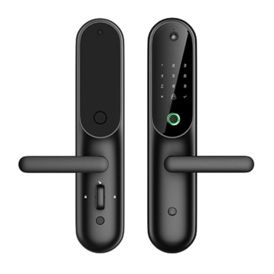
Page 4: Device Layout
Device Layout Camera LCD screen Keypad NFC Area Doorbell Reset Fingerprint Leave Scanner Home Button Auxiliary Lock Knob Note: NFC scanning is only available on the Crown Lock Plus model. Manual keyhole Emergency power USB input... - Page 5 ① Front panel (x1) ⑨ Spring for square spindle (x1) ② Connecting cylinder (x2) ⑩ Square spindle (x1) ③ Key Link Strip (x1) ⑪ Screws (x1) ④ Connecting cylinder (x1) ⑫ Plugs for screws (x1) ⑤ Square spindle (x1) ⑬ Battery cover (x1) ⑥...
-
Page 6: Specifications
Features • Communication Mode: IEEE 802.15.4 Zigbee. Supports multiple unlocking methods: Smart phone, pin code and fingerprint identification • (and NFC in Crown Lock Plus version). Supports linkage control: Allowing scenes to be set up to cater for different needs. •... -
Page 7: Preparation Before Installation
Preparation Before Installation Prior to installing the door lock, you need to determine the opening direction of the door, as there are some adjustments that may need to be made to the lock body, door handle orientation and the spindle rotation direction. Don’t worry if you get it wrong, as it’s easy enough to remove the lock from the door and re-adjust, if necessary. - Page 8 Lock Body Adjustment Having determined the door opening direction, we first need to adjust the direction of the door latch on the lock body, so that it will engage correctly when the door closes. The rule of thumb here is quite simple. Simply rotate the door latch so that its bevel (curved bit) points in the direction of the door frame, once it is fitted into the door.
- Page 9 Door Handle Orientation Depending on the door opening direction, you may need to rotate the handles on the front and rear plates of the door unit. The procedure below explains how to do this. 1) Using a Philips screwdriver, remove the screw holding the handle in place, as shown.
- Page 10 Adjust Spindle Clutch Finally, we need to adjust the spindle clutch on the Front Panel, to properly align with the door handle according to the door opening direction. Spindle Clutch Marked on this spindle clutch is an arrow. This arrow must point in the same direction as the handle (i.e.
- Page 11 Installing the Door Lock Installing the Lock Body 1) Measure the point where you wish to place the lock template – Typically, 1000mm to 1200mm from the bottom and 60mm from the edge of the door. 2) Mark this point. 3) Place the supplied template to line up the marker with the reference mark on the template.
- Page 12 7) Insert the Lock Body and make sure all the holes line up. 8) Screw the Lock Body in place. It’s now ready for the attachment of the front and rear door lock plates.
-
Page 13: Installing The Front Plate
Installing the Front Plate 1) Install the two connecting bolts. 2) Connect the cable interconnects (x2) and Large Square Spindle, lining up the holes on the spindle with the clutch. Insert the included pin and twist its ends to make sure the spindle cannot be pulled out. - Page 14 Installing the Back Plate 1) Attach the small square spindle. 2) Connect the cable interconnects (x2) to the connector on the back plate. 3) Affix the back plate to the door, making 4) Screw the back plate in place and insert the batteries.
- Page 15 Adding the Device to the Smart Home Network Use the Logika Smart Home app to add the device to the Smart Home system. Please refer to the Logika Smart Mobile App user guide which will take you through the process of adding smart devices to the system.
-
Page 16: Entering Admin Mode
User Administration and Security Entering Admin Mode 1) Tap the touchpad screen to wake it up. 2) Tap the * key twice in quick succession. 3) Enter the admin code (Default is 123456) followed by the # key. 4) The display will now show you some admin options that you can use. Note: Don’t forget to change the Admin passcode from the default for complete security! Set Time Once the door lock is connected to the Smart Home system (as described previously), the time will... -
Page 17: Unlocking The Door
Scene. For instance, you could engage the security cameras, turn off all the lights and heating, etc when you leave the house. Refer to the Logika Smart Mobile App user guide for information on how to set up a Scene. -
Page 18: Troubleshooting
The issue you are experiencing is not mentioned here. Please contact us at support@logika.nz with your issue and we will do our utmost to help!
Need help?
Do you have a question about the Smart Crown Lock and is the answer not in the manual?
Questions and answers