Table of Contents
Advertisement
Quick Links
Advertisement
Table of Contents

Related Manuals for FORTEZA FM-30(24)-C-BT


Summary of Contents for FORTEZA FM-30(24)-C-BT
- Page 1 JSC FORTEZA FORTEZA FM-30(24)-BT Security Sensors FM-30(24)-C-BT FM-30(24)-V-BT FM-30(24)-F-BT User manual Document Part Number 4372-43071246-087-07 Declaration of conformity ЕАЭС № RU Д-RU.ГР01.В.06594 2017 Please visit our internet sites: www.forteza.com www.forteza.eu Page 1...
-
Page 2: Table Of Contents
FORTEZA JSC FORTEZA FM-30(24)-BT TABLE OF CONTENTS 1 Introduction 2 Purpose 3 Specifications 4 Sensor components 5 Operation 5.1Principle of operation 6 Sensor construction 7 Safety measures 8 Mounting 8.1Requirements for the protected site 8.2Requirements for the protected building 8.3Mounting on the perimeter site 8.4Mounting on the wall... -
Page 3: Introduction
FORTEZA JSC FORTEZA FM-30(24)-BT 1 ... INTRODUCTION The user manual contains the following information about the microwave monostatic security sensor FM-30(24)-C-BT, FM-30(24)-F, FM-30(24)-V-BT: Purpose and principle of operation Sensor components and possible delivery sets Sensor specifications and its components Operating and servicing rules There is the information about tare, packaging and conditions of the sensor transportation. -
Page 4: Purpose
FORTEZA JSC FORTEZA FM-30(24)-BT 2 PURPOSE 2.1 The purpose of the sensor is to protect perimeter sites, open and closed grounds of different objects and to detect an intruder moving upright or bent in the detection zone. Application of the sensor on objects with a high electromagnetic radiation is to check by the trial operation. -
Page 5: Sensor Components
FORTEZA JSC FORTEZA FM-30(24)-BT the absence of supply voltage. The alarm is generated by breaking the actuating optoelectronic relay contacts for 3 sec minimum. This signal is transmitted by the yellow and pink wires. 3.5 The characteristics of the actuating optoelectronic relay are: the maximum switching current is 0,1 A;... -
Page 6: Operation
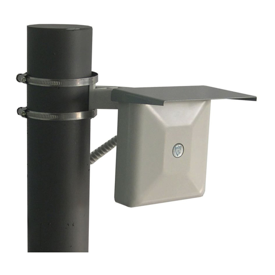
- power supply unit PSU-U-15-0,15 - junction box JB-15 or JB-30 - SUPPORT-2 (SUPPORT-2,5, SUPPORT-3, SUPPORT-3,5) *The software you can download on our website www.forteza-eu.com. 5 OPERATION 5.1 Principle of operation. The principle of operation is based on the method of linear frequency modulation, where the generator operating frequency is changed linearly within small range. - Page 7 FORTEZA JSC FORTEZA FM-30(24)-BT the cover 6 to get the access to the adjustment and indication elements. The sensor is connected to the receiving-control device with cable 8 stretched through cable gland14 and corrugated pipe 7. 6.2 The transceiver unit is mounted on support 1 with bracket and buckles 13 as shown in fig.
- Page 8 FORTEZA JSC FORTEZA FM-30(24)-BT 1- support -1 pc 8- cable -1 pc 2- bracket -1 pc 9- bolt M6x35 -1 pc 3- bushing -1 pc 10- nut M6 -1 pc 4- base -1 pc 11- washer 6 -2 pcs 5- case...
- Page 9 FORTEZA JSC FORTEZA FM-30(24)-BT 7- corrugated pipe -1 pc 14- cable gland -2 pcs ..15- protective visor -1 pc Fig. 6.1 Mounting on a support 7- bolt М6х35 1- fence -1 pc 1 pc 2- bracket -1 pc 8- ring 1 pc 9- nut М6...
-
Page 10: Safety Measures
FORTEZA JSC FORTEZA FM-30(24)-BT 7 SAFETY MEASURES 7.1 The current safety standards for the operation with electrical facilities with the voltage up to1000 V should be observed during mounting, preventive maintenance and repair of the sensor. 7.2 Cables should be laid, terminated and connected to the sockets only when the supply voltage is OFF. -
Page 11: Requirements For The Protected Building
FORTEZA JSC FORTEZA FM-30(24)-BT 8.2 Requirements for the protected building. a) sensors should not be mounted on walls subjected to constant vibrations b) animals, birds, vibrating or moving objects (vent lights, doors, air-exhausters, etc.) should not be in the protected room. - Page 12 FORTEZA JSC FORTEZA FM-30(24)-BT Fig. 8.1 Detection zone parameters of the modification Volume at the height of 1 m Please visit our internet sites: www.forteza.com www.forteza.eu Page 12...
- Page 13 FORTEZA JSC FORTEZA FM-30(24)-BT Fig. 8.2 Detection zone parameters of the modification Curtain at the height of 1 m Fig. 8.3 Detection zone parameters of the modification Fan at the height of 1 m Please visit our internet sites: www.forteza.com www.forteza.eu...
-
Page 14: Mounting On The Wall
FORTEZA JSC FORTEZA FM-30(24)-BT The dimensions and the detection zone configurations are given for the ideal conditions of the perimeter area without taking into account the ambient conditions. Practically the dimensions and the detection zone configurations can differ from the given ones because of ambient objects, reflecting surfaces and the detection sensitivity. - Page 15 FORTEZA JSC FORTEZA FM-30(24)-BT Table 9.1 Cable color Purpose white Supply plus (+) brown Supply minus (-) yellow Relay contacts pink purple Tamper circuit (TAMPER) black green Remote control (RC) blue RS-485 «B» RS-485 «A» grey Bluetooth activation To activate the Remote Control energize the green RC wire of the output cable with voltage from 10 up to 30 VDC for 1 sec.
- Page 16 FORTEZA JSC FORTEZA FM-30(24)-BT Fig. 9.1 Connection diagram using LGU-4 The micro switch positions and the detection zone length are given in Table 9.2. Table 9.2 Subzone number Subzone range from the sensor 0-2,5 m 2,5-5 m 5-7,5 m 7,5-10 m...
-
Page 17: Adjustment With A Pc
FORTEZA JSC FORTEZA FM-30(24)-BT 27,5-30 m 9.2 The DETECTION ZONE LIMITATION or the “APPROVED PASSAGES”, i.e. subzone disconnection is performed with a PC. If the corresponding subzone is switched OFF, the sensor does not generate an alarm if the detection zone is crossed in this place. - Page 18 FORTEZA JSC FORTEZA FM-30(24)-BT Fig.10.1 Fig.10.2 Choose the folder COM-PORT in window of Search and Installation Options Please visit our internet sites: www.forteza.com www.forteza.eu Page 18...
- Page 19 FORTEZA JSC FORTEZA FM-30(24)-BT Fig.10.3 Fig.10.4 Click Finish and the sensor is ready for use. Please visit our internet sites: www.forteza.com www.forteza.eu Page 19...
- Page 20 FORTEZA JSC FORTEZA FM-30(24)-BT After COM-PORT installation it is necessary to know its number. Please follow: START →OPTIONS →CONTROL PANEL→SYSTEM→DEVICE→DEVICES MANAGER→PORT (COM and LPT) →USB SERIAL PORT and remember the number. 10.3 Sensor Control Program installation To install the program please start ConfigMaster_setup.exe.
- Page 21 FORTEZA JSC FORTEZA FM-30(24)-BT Install the program following the instructions: Fig. 10.6 Fig. 10.7 Please visit our internet sites: www.forteza.com www.forteza.eu Page 21...
- Page 22 FORTEZA JSC FORTEZA FM-30(24)-BT Fig. 10.8 The installation of ConfigMaster is finished. Please visit our internet sites: www.forteza.com www.forteza.eu Page 22...
- Page 23 FORTEZA JSC FORTEZA FM-30(24)-BT Click on ConfigMaster with the right mouse button and choose PROPERTIES. Open the insert CONSISTENCY and make sure that you have checked the point «Run the program in the name of Administrator». 10.4 Computer-controlled operation. Connect the sensor to the computer with the USB cable and apply power to the sensor. From the desktop run the program ConfigMaster.
- Page 24 FORTEZA JSC FORTEZA FM-30(24)-BT There is an automatic search for connected sensors. If the sensors are not found, it will appear the window shown in Fig. 10.10. Fig. 10.10 If the automatic search is selected, the search starts immediately. If the search fails, check the power supply and connect the detector to the PC.
- Page 25 FORTEZA JSC FORTEZA FM-30(24)-BT Fig. 10.11 If the «PC Control» not ticked, the program displays the state of control devices, signal and noise level in every sub-zone, and the sensor is managed with built-in control devices. This mode let control the sensors settings and its operation visually.
- Page 26 FORTEZA JSC FORTEZA FM-30(24)-BT Fig. 10.12 The program window displays the signal levels in the subzones, 12 independent thresholds controllers in the subzones, the switch «Operation/Settings», the button «Save to Memory» and «Return to the factory settings». You also can switch ON or OFF the subzones.
- Page 27 FORTEZA JSC FORTEZA FM-30(24)-BT Fig. 10.13 In the status line you can see the information about connection (port number, logic number, port status), sensor and version of the software. You can change the logic number (address) of the sensor if you need. Click the right mouse button in the main program window and choose the menu option «Change the logic...
- Page 28 FORTEZA JSC FORTEZA FM-30(24)-BT Fig. 10.14 Let us give an example how to work with the program configurating a complex detection zone. Task: to configurate the detection zone 20 m long with approved passages in 4 and 5 subzones. To set up a sensor two persons are needed.
- Page 29 FORTEZA JSC FORTEZA FM-30(24)-BT passages should be made in the second half of each subzone. The subzones, where it is physically impossible make control passages, are not configurated. After you have set up the signal gain, the noise level should not be higher than 20% of the full scale.
-
Page 30: 11Adjustment With Bluetooth
1. Start Play Market, set in type in the search line (please check the connection of the Android device to the Internet). After that the Software installation is finished. 2. Download the APK-file from the website htpp://forteza-eu.com/. To install the program APK-file “FM UNI” please record the to the Android-device and start it. - Page 31 FORTEZA JSC FORTEZA FM-30(24)-BT In this menu you can choose a type of connection and operating language. There are two ways connection: wired (via USB) and wireless (via Bluetooth). 11.3 Connection via USB. The mobile device should have an OTG slot.
- Page 32 FORTEZA JSC FORTEZA FM-30(24)-BT Fig. 11.3 Press the button “Connect” and it will appear the access permission to the USB-device – Figure 11.4. Fig. 11.4 Please visit our internet sites: www.forteza.com www.forteza.eu Page 32...
- Page 33 FORTEZA JSC FORTEZA FM-30(24)-BT If the message “No connected USB-devices” appears, please check the connection of the USB-cable and the power of the sensor. Press “Yes”. After the successful connection the button “Connect” will change into “Start the data exchange” – Figure 11.5 Fig.
- Page 34 FORTEZA JSC FORTEZA FM-30(24)-BT Fig. 11.6 Press the button “Device search” and the automatically search starts – Figure 11.7 Fig. 11.7 Upon search completion please choose a device from the list by click – Figure 11.8 Fig.11.8 It will open the work window. If no devices were found, please check the power of the sensor and connection of the Bluetooth-cable.
- Page 35 FORTEZA JSC FORTEZA FM-30(24)-BT 11.5 Work with the program FM UNI. The main view of the program is given on fig.11.9 Fig. 11.9 The program window displays the signal levels and interferences in the subzones and the switches “Operation” and “Settings”.
- Page 36 FORTEZA JSC FORTEZA FM-30(24)-BT The button “Save all the parameters” saves all changes in the device permanent memory. The “Logical Number” field is used to display and switch the logical number of the sensor. To change the logical number, simply select a new logical number from the list - Figure 11.10...
- Page 37 FORTEZA JSC FORTEZA FM-30(24)-BT Fig. 11.11 By setting of sensitivity it is not allowed any movements of things or objects in the detection zone except of the operator making the control passages. The first operator makes control passages in the second half of every subzone and the second one achieves a sure alarm generating with special regulators, while the signal level should be approximately the same in all subzones and be 90 ...
-
Page 38: Maintenance
FORTEZA JSC FORTEZA FM-30(24)-BT 12 Maintenance. 12.1 Maintenance of the sensor is made by the staff specially trained and instructed. 12.2 During exploitation of the sensor it is necessary to make monitoring and prevention works periodically. 12.2.1 Every month: check the appearance of the sensor. It is necessary to check if there is no dust, dirt, snow and ice on the transceiver and clean them if necessary. -
Page 39: Troubleshooting Guide
FORTEZA JSC FORTEZA FM-30(24)-BT 13 TROUBLESHOOTING GUIDE List of possible troubles is given in Table 13.1. Table 13.1 Trouble Possible Cause Repair 1. The receiving- control Check the cable integrity and Disconnection device constantly accuracy actuating relay circuit. generates an alarm. -
Page 40: Storage
FORTEZA JSC FORTEZA FM-30(24)-BT 14 STORAGE The storage of the sensor in the package for the transportation must meet the requirements 3 of the storage in non-heated premises according to GOST 15150. During storage the influence of hostile environment should be prevented. - Page 41 FORTEZA JSC FORTEZA FM-30(24)-BT Manufacturer contact details: Manufacturer: OOO Okhrannaya technika (holder of the trademark Forteza) Location: Latitude 53°11'13.69"С, Longitude 45°12'18.51"В Postal address: 442960, Russia, Zarechny, Penza region, P.O. box 45 Tel.: +7 8412 655316 Fax: +7 8412 655317 E-mail: info@forteza-eu.com...
Need help?
Do you have a question about the FM-30(24)-C-BT and is the answer not in the manual?
Questions and answers