Table of Contents
Advertisement
Quick Links
Installation Directions
2. Power Cord
3. Magnet Ring
4. Power Input
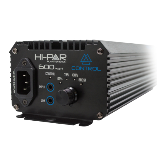
1. Digital Ballast
8. Connect
7. Dimming Knob
Link Cable
STATUS
LED
Output lock down
1 Flash
Output errors
2 Flash
Low input voltage
3 Flash
Over temperature
4 Flash
High input
5 Flash
Note: When the controller is connected the CONTROL indicator LED ashes 2 times every 2
seconds - indicating controller is functioning correctly. However, if the Connect Link Cable is
removed during operation the ballast will shut down after 3 minutes. When operating
ballast without a HI-PAR Control Station the CONTROL indicator LED will be o . Turn power
o and on to reset the ballast when either connecting or disconnecting the Control Station.
MAINS POWER
MIN
MAX
BOOST
669
711
100%
615
657
75%
456
498
60%
361
402
E40 and DE
lamp compatible
5. OUTPUT to
HPS or MH lamp
6. Rubber Feet
BOX CONTENT:
1 x 600w Digital Ballast
1 x Power Cord
1 x Connect Link Cable
4 x Rubber Feet
1 x User Manual
LAMP POWER
MIN
MAX
BOOST
639
681
100%
579
621
75%
429
471
60%
339
381
USER MANUAL
HP600E Control for HPS and MH lamps
Data is based on operation of a standard HPS/MH lamp.
Supply power is based on typical commercial 240V,50/60Hz.
Performance
Model
Max Input
THD
Model
Voltage
Power
(V)
(W)
HP600E
240V
711
<10%
Control
Maximum
Power
Working
Ignitor
Current
Factor
Voltage
Voltage
(A)
(COSθ)
(V)
(kV)
3.0
.99
216-264
4.0
Advertisement
Table of Contents

Related Manuals for Hi-Par HP600E Control


Summary of Contents for Hi-Par HP600E Control
- Page 1 3 minutes. When operating ballast without a HI-PAR Control Station the CONTROL indicator LED will be o . Turn power o and on to reset the ballast when either connecting or disconnecting the Control Station.
- Page 2 CONTROL STATION Compatible - Plug and Play Linkable 400 Fixture - 200 Ballast on each channel Connecting the Ballast to the HI-PAR ‘Control Station’ (controller - sold separately) THERMO SENSOR THERMO SENSOR - Control Station communicates with ballast via TRS (Stereo) cable - Multiple ballasts can be installed in ‘daisy-chain’...
Need help?
Do you have a question about the HP600E Control and is the answer not in the manual?
Questions and answers