Advertisement
Quick Links
Advertisement

Related Manuals for peerless-AV SC560DPB


Summary of Contents for peerless-AV SC560DPB
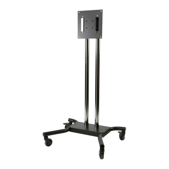
- Page 1 Installation and Assembly: 32" - 65" Flat Panel Display Cart Models: SC560DPB, SC560DPS Max UL Load Capacity: 115 lb (52 kg) display 2300 White Oak Circle • Aurora, Il 60502 • (800) 865-2112 • Fax: (800) 359-6500 • www.peerless-av.com ISSUED: 08-31-11 SHEET #: 009-9053-7 07-25-12...
-
Page 2: Table Of Contents
NOTE: Read entire instruction sheet before you start installation and assembly. WARNING • Do not begin to install your Peerless product until you have read and understood the instructions and warnings contained in this Installation Sheet. If you have any questions regarding any of the instructions or warnings, for US customers please call Peerless customer care at 1-800-865-2112, for all international customers, please contact your local distributor. -
Page 3: Parts List
Before you begin, make sure all parts shown are included with your product. Parts List SC560DPB SC560DPS Part Number Description Qty. Part Number column bracket 009-1419 009-1419 adapter plate 009-1599 009-1599 column base 009-1484 009-1484 column 009-1394 009-5452 right leg... - Page 4 Adapter Bracket Fasteners M5 x 12 mm (4) M6 x 12 mm (4) (520-1027) (520-1128) M8 x 12 mm (4) .75" spacer (4) (520-9571) (540-1059) M5 x 25 mm (4) M6 x 25 mm (4) M8 x 25 mm (4) (520-9543) (520-1208) (520-1031)
-
Page 5: Assembling Cart
Insert right leg (E) into column base (C) as shown in fi gure 1.1. Then line up holes of right leg with holes in column base. Fasten right leg to column base using two 3/8-16 x 1-1/2" bolts (G) and two joint connectors (H), tighten using 3/16"... - Page 6 Insert columns (D) over column base supports (C) Insert two 1/4-20 x 12mm socket screws (L) into and align cable management holes. Secure columns column bracket (A) using 4mm allen wrench (N), to column base supports using four 5/16" socket leaving 3/16"...
-
Page 7: Installing Adapter Plate
Installing Adapter Plate WARNING • Tighten screws so adapter plate is fi rmly attached. Do not tighten with excessive force. Overtightening can cause stress damage to screws, greatly reducing their holding power and possibly causing screw heads to become detached. Tighten to 40 in. • lb (4.5 N.M.) maximum torque. •... - Page 8 Attaching Display using VESA 100, 200 or VESA 300 Mounting Pattern WARNING • If screws don't get three complete turns in the display inserts or if screws bottom out and adapter plate is still not tightly secured, damage may occur to display or product may fail. For Flat Back Display Select the screws from the baffl...
-
Page 9: Mounting Flat Panel Display
Mounting Flat Panel Display Attach adapter plate (B) onto 1/4-20 screws of column bracket (A). Insert two 1/4-20 x 12mm screws (L) into top holes indicated below for desired display orientation. Adjust display then secure with two 1/4-20 x 12mm screws (L). Tighten all screws using 4mm allen wrench (N). No Tilt 2°... -
Page 10: Cable Management
ISSUED: 08-31-11 SHEET #: 009-9053-7 07-25-12 © 2012, Peerless Industries, Inc. All rights reserved. All other brand and product names are trademarks or registered trademarks of their respective owners. Peerless Industries, Inc. 2300 White Oak Circle Aurora, Il 60502 www.peerless-av.com... - Page 11 Limited Warranty or impose any obligation on Peerless in connection with the sale of any Peerless® product. This warranty gives specifi c legal rights, and you may also have other rights which vary from state to state. www.peerless-av.com © 2012 Peerless Industries, Inc.
Need help?
Do you have a question about the SC560DPB and is the answer not in the manual?
Questions and answers