Table of Contents
Advertisement
Quick Links
Features
Ultra Compact size (30.0 x 20.0 mm)
MCU less Tranceiver module with SPI interface
High RX sensitivity (-103 dBm)
Outperforming link budget (up to +112 dB)
Up to +9.0 dBm output power
Very low power consumption:
8.7 mA in RX mode
27 mA in TX mode
0.7 µA in sleep mode
Internal Clock Output
Preassigned Atmel
Capability to use MAC address into the onboard EEPROM
®
IEEE
900MHz ISM band
Rapid design-in with built-in Chip Antenna
RF Test point using MS-147 RF connector
Small physical footprint and low profile for optimum fit in very small application
boards
Mesh networking capability
Easy-to-use low cost development kit
Single source of support for HW and SW
Worldwide license-free operation
Note:
1. MCU is in active state with 3V Supply, CPU clock @ 16MHz, RX RPC enabled (for RX current),
PHY_TX_PWR=0x0 (for TX current), All digital outputs pulled high.
2. Controller Sleep Mode – SLEEP_MODE_PWR_DOWN
Note:
ZIGBIT 900 MHZ WIRELESS MODULES
(1)
(1)
(2)
®
MAC address that can be used on end product
802.15.4 compliant Transceiver
ATZB-RF-212B-0-CN
DATASHEET
Advertisement
Table of Contents

Related Manuals for Atmel ZIGBIT ATZB-RF-212B-0-CN

Summary of Contents for Atmel ZIGBIT ATZB-RF-212B-0-CN
- Page 1 27 mA in TX mode 0.7 µA in sleep mode Internal Clock Output ® Preassigned Atmel MAC address that can be used on end product Capability to use MAC address into the onboard EEPROM ® IEEE 802.15.4 compliant Transceiver...
-
Page 2: Table Of Contents
Table of Contents 1. Introduction ..................3 Summary ......................3 Applications ....................... 3 Abbreviations and acronyms ................3 Related documents ................... 4 2. ZigBit Module Overview ..............6 Overview ......................6 3. Specification..................8 Electrical Characteristics ................... 8 3.1.1 Absolute Maximum Ratings ..............8 3.1.2 Power Supply .................. -
Page 3: Introduction
700/800/900 MHz ISM band Transceiver alone on a very compact Module design that provides the customer to integrate the module to any of the recommended Atmel’s Microcontrollers that the application fits. The radio transceiver provides high data rates from 20 kb/s up to 1 Mb/s, frame handling, outstanding receiver sensitivity and high transmit output power enabling a very robust wireless communication. -
Page 4: Related Documents
High Frequency HVAC Heating, Ventilating, and Air Conditioning Hardware Inter-Integrated Circuit IEEE Institute of Electrical and Electronics Engineers Interrupt Request Industrial, Scientific and Medical radio band JTAG Digital interface for debugging of embedded device, also known as IEEE 1149.1 standard interface Medium Access Control layer Microcontroller Unit. - Page 5 [2] IEEE Std 802.15.4-2003 IEEE Standard for Information technology - Part 15.4 Wireless Medium Access Control (MAC) and Physical Layer (PHY) Specifications for Low-Rate Wireless Personal Area Networks (LR-WPANs) [3] ZigBee Specification. ZigBee Document 053474r17, October 19, 2007 [4] AT86RF212B Datasheet in http://www.atmel.com/devices/AT86RF212B.aspx?tab=documents Error! Reference source not found. [ZigBit 900 MHz Wireless Modules]...
-
Page 6: Zigbit Module Overview
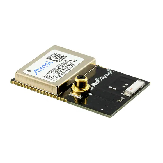
The ATZB-RF-212B-0-CN ZigBit is a compact, low-power, high sensitivity IEEE 802.15.4/ZigBee OEM module. Based on a solid combination of the latest Atmel MCU Wireless hardware platform, 900 MHz ISM band transceiver and Atmel Studio Wireless Composer - the ZigBit offers an unmatched combination of superior radio performance, ultra-low power consumption and exceptional ease of integration. - Page 7 Every ZigBit Module come pre loaded with Atmel assigned 64-bit MAC address stored in the signature bytes of the device. This unique IEEE MAC address can be used as the MAC address of the end product, so there is no need to buy a MAC address separately for the product using the ZigBit.
-
Page 8: Specification
Specification Electrical Characteristics 3.1.1 Absolute Maximum Ratings (1)(2) Table 3-1. Absolute Maximum Ratings Parameter Minimum Maximum Voltage on any pin, except RESET with respect to ground -0.3V 3.6V (V DD max Input RF level +10 dBm Current into Vcc pins 200 mA Absolute Maximum Ratings are the values beyond which damage to the device may occur. -
Page 9: Rf Characteristics
3.1.3 RF Characteristics Table 3-3. RF Characteristics Parameter Condition Range Unit Frequency band 902 to 928 Numbers of channels (FCC and Industry Canada) Channel spacing Transmitter output power Adjusted in 36 steps -25 to +11 Receiver sensitivity PER = 1% -103 On-air data rate 20, upto 1000... -
Page 10: Physical/Environmental Characteristics And Outline
Physical/environmental characteristics and outline Table 3-5. Physical characteristics. Parameters Value Comments Size 30.0 x 20.0 mm Operating temperature range -40°C to +85°C -40°C to +85°C operational Pin configuration Table 1 ATZB-RF-212B-0-CN Pinout description Pin Out descriptions Function AVSS Analog Ground AVSS Analog Ground DEVDD... -
Page 11: Antenna Orientation Recommendation
Antenna Orientation Recommendation The Antenna in this module is designed to provide the best possible LoS range in the direction indicated in this illustration. Mounting information The Figure below shows the PCB layout recommended for a ZigBit module. Neither via-holes nor wires are allowed on the PCB upper layer in the area occupied by the module. - Page 12 Figure 3-1. ATZB-RF-212B-0-CN Dimensions Error! Reference source not found. [ZigBit 900 MHz Wireless Modules]...
- Page 13 Figure 3-2. ATZB-RF-212B-0-CN Pinout Error! Reference source not found. [ZigBit 900 MHz Wireless Modules]...
- Page 14 Figure 3-3. ATZB-RF-212B-0-CN Footprint Dimensions Error! Reference source not found. [ZigBit 900 MHz Wireless Modules]...
- Page 15 Figure 3-4. ATZB-RF-212B-0-CN Mounting Information Error! Reference source not found. [ZigBit 900 MHz Wireless Modules]...
-
Page 16: Soldering Profile
The ZigBit’s location and orientation on the carrier board is illustrated in the above PCB Land pattern and Mounting information drawing. The Recommended placement of ZigBit on Carrier Board needs to be accurately followed to ensure performance on the end application Soldering profile The J-STD-020C-compliant soldering profile is recommended according to Table... -
Page 17: Antenna Reference Designs
Antenna reference designs Multiple factors affect proper antenna match, hence, affecting the antenna pattern. The particular factors are the board material and thickness, shields, the material used for enclosure, the board neighborhood, and other components adjacent to antenna. Following guidelines need to be followed when designing the base board for the ZigBit. General Recommendations: ... -
Page 18: Persistence Memory
Note: 1 The MAC address stored inside the AT24MAC602 is a uniquely assigned ID for each ZigBit and owned by Atmel. User of the ZigBit application can use this unique MAC ID to address the ZigBit in end-applications. The MAC ID can be read from the ZigBit using the Performance Analyzer Application that can be downloaded from www.atmel.com/wireless... -
Page 19: Agency Certifications
Agency Certifications United States (FCC) This equipment complies with Part 15 of the FCC rules and regulations. To fulfill FCC Certification requirements, an OEM manufacturer must comply with the following regulations: The ATZB-RF-212B-0-CN modular transmitter must be labeled with its own FCC ID number, and, if the FCC ID is not visible when the module is installed inside another device, then the outside of the device into which the module is installed must also display a label referring to the enclosed module. - Page 20 This equipment complies with radio frequency exposure limits set forth by Industry Canada for an uncontrolled environment. This equipment should be installed and operated with minimum distance 20 cm between the device and the user or bystanders. Cet équipement est conforme aux limites d'exposition aux radiofréquences définies par Industrie Canada pour un environnement non contrôlé.
-
Page 21: Appendix A. Revision History
Revision history Appendix A. Doc. Rev. Date Comments 16.Jul.13 Internal Initial release 24.Dec.13 Added more sections Error! Reference source not found. [ZigBit 900 MHz Wireless Modules]... - Page 22 Atmel Corporation or its subsidiaries. Other terms and product names may be trademarks of others. Disclaimer: The information in this document is provided in connection with Atmel products. No license, express or implied, by estoppel or otherwise, to any intellectual property right is granted by this document or in connection with the sale of Atmel products.
Need help?
Do you have a question about the ZIGBIT ATZB-RF-212B-0-CN and is the answer not in the manual?
Questions and answers