Table of Contents
Advertisement
CEILING DUCT TYPE AIR CONDITIONERS
INSTALLATION INSTRUCTIONS
• This unit is charged with new refrigerant, R407C.
• Be sure to use proper tools for R407C, when installing the unit.
• Please read this instruction sheet completely before installing the product.
• When the power cord is damaged, replacement work shall be performed by authorized
personnel only.
• Installation work must be performed in accordance with the national wiring standards by
authorized personnel only.
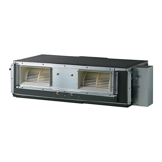
Indoor Unit
Outdoor Unit
(Side)
Air intake
vents
Air outlet
vents
(Refrigerant : R407C)
Air outlet vents
Air intake vents
Remote Controller
(Rear)
(Side)
Air intake vents
Air outlet vents
Control Cover
Connecting Wire
Connection Pipe
Drain Hose
Air filters
(Rear)
Control cover
Connecting wire
Piping
Drain hose
P/No.:
MFL65000405
Advertisement
Table of Contents

Subscribe to Our Youtube Channel
Related Manuals for LG FB-C186HSA0


Summary of Contents for LG FB-C186HSA0
- Page 1 CEILING DUCT TYPE AIR CONDITIONERS INSTALLATION INSTRUCTIONS (Refrigerant : R407C) • This unit is charged with new refrigerant, R407C. • Be sure to use proper tools for R407C, when installing the unit. • Please read this instruction sheet completely before installing the product. •...
-
Page 2: Table Of Contents
OUT-LINE OF INSTALLATION 1. The following should be always observed for safety ......3 Installation works Installation Parts Required tools 2. Installation of Indoor, Outdoor unit • • 1) Selection of the best Four Type “A” screws Level • • location......4 Connecting cable Screw driver •... -
Page 3: The Following Should Be Always Observed For Safety
1. The following should be always observed for safety • Please report to or take consent by the supply authority before connecting to the system. • Be sure to read "THE FOLLOWING SHOULD BE ALWAYS OBSERVED FOR SAFETY" before installing the air conditioner. •... -
Page 4: Installation Of Indoor, Outdoor Unit
2. Installation of Indoor, Outdoor Unit 1. Selection of the best location Inspection hole Top view (600X600) 1) Indoor unit (unit: mm) Control box Select location Install the air conditioner in the location that satisfies the following conditions. • The place shall easily bear a load exceeding four times the indoor unit’s weight. -
Page 5: Indoor Unit Installation
2. Indoor unit installation ■Installation of Unit Install the unit above the ceiling correctly. CASE 1 POSITION OF SUSPENSION BOLT • Apply a joint-canvas between the unit and duct to absorb unnecessary vibration. • Apply a filter Accessory at air return hole. (Unit:mm) Dimension F (G) H... - Page 6 • Select and mark the position for fixing bolts. • Drill the hole for set anchor on the face of ceiling. • Insert the set anchor and washer onto the suspension bolts for locking the Old building New building suspension bolts on the ceiling. •...
- Page 7 CAUTION 1. Install declination of the indoor unit is very important for the drain of the duct type air conditioner. 2. Minimum thickness of the insulation for the connecting pipe shall be 5mm. Front of view • The unit must be horizontal or declined to the drain hose connected when finished installation.
- Page 8 • Drill the piping hole with 70mm dia, hole WALL Indoor Outdoor core drill. • Piping hole should be slightly slant to the outdoor side. 5~7mm INSULATION, OTHERS Insulate the joint and tubes completely. THERMAL INSULATION All thermal insulation must comply with local requirement. INDOOR UNIT Union for liquid pipe Thermal insulator for refrigerant pipe...
- Page 9 Install the remote control box and INSTALLATION OF REMOTE CONTROL BOX cord correctly. POINT OF REMOTE CONTROLLER INSTALLATION • Although the room temperature sensor is in the indoor unit, the remote control box should be installed in such places away from direct sunlight and high humidity. INSTALLATION OF THE REMOTE CONTROL BOX ROUTING OF THE REMOTE CONTROL CORD •...
- Page 10 WIERED REMOTE CONTROLLER INSTALLATION • Since the room temperature sensor is in the remote controller, the remote controller box should be installed in a place away from direct sunlight, high humidity and direct supply of cold air to maintain proper space temperature. Install the remote controller about 5ft(1.5m) above the floor in an area with good air circulation at an average temperature.
- Page 11 Perform the work according to the Service REFRIGERANT PIPING Manual or Installation Guide. • Use two spanners when connect the refrigerant pipe to the unit. Flared connection (Union) • Make a bend with a radius as large as possible. Use a seemliness tube •...
- Page 12 Perform the electrical wiring work according to ELECTRICAL WIRING the electrical wiring connection. • All wiring must comply with local requirements. Circuit Breaker • Select a power source that is capable of Main power source supplying the current required by the air Switch box conditioner.
- Page 13 Perform the electrical wiring work according to ELECTRICAL WIRING the electrical wiring connection. • All wiring must comply with local requirements. Circuit Breaker Main • Select a power source that is capable of power source Switch box supplying the current required by the air conditioner.
-
Page 14: Connecting Pipes To The Indoor Unit
3. Connecting Pipes to the Indoor Unit 3-1. Preparation of Piping Copper Main cause of gas leakage is defect in Slanted Uneven Rough tube 90° flaring work. Carry out correct flaring work in the following procedure. 1) Cut the pipes and the cable. ■Use the accessory piping kit or the pipes purchased locally. - Page 15 6) Pipe bending Annealed copper pipe with small diameter (ø6.35 or ø9.52) can be easily bent manually. In this case, secure large R(radius) for the bend section and gradually bend pipe. If annealed copper pipe is large in diameter (ø15.88 or ø19.05), bend pipe with bender. Use bender appropriate for the pipe diameter.
-
Page 16: Connecting Pipes To The Outdoor Unit
4. Connecting Pipes to the Outdoor Unit 1) Connecting the pipes to the Outdoor unit 1. Align the center of the pipings and sufficiently tighten the flare nut with fingers. 2. Finally, tighten the flare nut with torque wrench until the wrench clicks. •... -
Page 17: Connecting Cables Between Indoor Unit And Outdoor Unit
6. Connecting Cables between Indoor Unit and Outdoor Unit 1) Connecting cables to the Indoor Unit ■Connect the wires to the terminals on the control board individually according to the outdoor unit connection. • Ensure that the color of the wires of outdoor unit and the terminal No. are the same as those of indoor unit respectively 18k/24k/30k/36kBtu/h •... -
Page 18: Outdoor Unit
3) Connecting the cable to the Outdoor Unit Outdoor unit 1. Remove the Cover control from the unit Terminal block by loosening a screw. Connect the wires to the terminals on Cord Clamper the control board individually as following. 2. Secure the cable onto the control board Over 5mm with the holder (clamper). -
Page 19: Form The Pipings
4) Form the pipings 1. Wrap the connecting portion of indoor Seal a small opening unit with the Insulation material and around the pipings with gum type sealer. secure it with two Plastic Bands. (for the right pipings) Drain hose Taping •... -
Page 20: Air Purging Of The Connecting Pipes And The Indoor Unit
7. Air Purging of the Connecting Pipes and the Indoor Unit The air which contains moisture remaining in the refrigeration cycle may cause a malfunction on the compressor. 1. Confirm that both the liquid side valve and the gas side valve are set to the closed position. 2. -
Page 21: Group Control
8. Group Control It operates maximum 16 Units by only one Wired Remote Controller, and each Unit starts sequentially to prevent overcurrent. Main PCB Indoor Unit 1 Indoor Unit 2 Indoor Unit 16 Terminal(Local Supply) Terminal(Local Supply) Terminal(Local Supply) Block Block Block Connector... -
Page 22: External Static Pressure) Setting
10. E.S.P.(External Static Pressure) Setting Open the rear cover of the wired remote-controller to set the mode. Select one of three selectable modes as follows. Without Zone System 1. Position V-H, F-H: • This position sets the maximum E.S.P as a default set. 2. -
Page 23: How To Set E.s.p
11. How to Set E.S.P? Procedure of RPM change: Ex) External Static Pressure is 6mmAq for Model Name "FB-C186HSA0" • To protect the unit, compressor is designed to be off during E.S.P. setting. Push the "On/Off" button. The unit will start. - Page 24 [Table. 1] Static Pressure(mmAq) Setting Value Model Name Step CMM(CFM) 16.0(565) FB-C186HSA0 14.5(512) 13.0(459) 18.0(636) FB-C246HSA0 16.5(583) 14.0(494) 28.0(988) FB-C306GSA0 26.0(918) 24.0(847) 32.0(1130) FB-C366GSA0 29.0(1024) FB-C426GSA0 26(918) 40(1414) FB-C488RSA0 35(1237) 30(1060) 48(1696) FB-C608RSA0 43(1520) 38(1343) Note: 1. To get the desired Airflow & E.S.P combination from the table set the matching value from the table.
Need help?
Do you have a question about the FB-C186HSA0 and is the answer not in the manual?
Questions and answers