Table of Contents
Advertisement
Quick Links
Advertisement
Table of Contents

Subscribe to Our Youtube Channel
Related Manuals for WinSystems ITX-F-3800

Summary of Contents for WinSystems ITX-F-3800
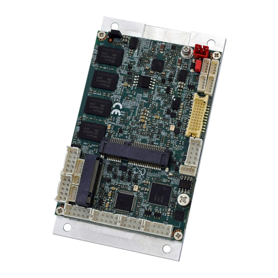
- Page 1 ITX-F-3800 Ultra Small Form Factor Single Board Computer with ® Intel Atom™ E3825 (Dual Core) CPU, 10/100/1000 Ethernet, Mini-PCIe, USB, and COM Product Manual WinSystems, Inc. | 715 Stadium Drive, Arlington, Texas 76011 | 817-274-7553 | info@winsystems.com | www.winsystems.com...
- Page 2 No part of this document may be copied or reproduced in any form or by any means without the prior written consent of WinSystems, Inc. The information in the document is subject to change without notice. The information furnished by WinSystems, Inc. in this publication is believed to be accurate and reliable.
-
Page 3: Table Of Contents
ITX-F-3800 Table of Contents Before You Begin ......... 5 Warnings . - Page 4 ITX-F-3800 7.5.2 JVL1 - eDP Panel Power Select ..........24 BIOS Functionality .
-
Page 5: Before You Begin
Practices” on page 40) when using and handling the WinSystems ITX-F-3800. Following these recommendations provides an optimal user experience and prevents damage. Read through this document and become familiar with the ITX-F-3800 before proceeding. FAILING TO COMPLY WITH THESE BEST PRACTICES MAY DAMAGE THE ITX-F-3800 AND VOID YOUR WARRANTY. -
Page 6: Features
ITX-F-3800 a great choice for small human machine interface (HMI) applications. Considering the small size of the ITX-F-3800, it is packed with I/O features often lacking from larger SBCs. It includes a 10/100/1000 Ethernet controller based on the Intel i211 family with wake-on-LAN and PXE capabilities, connectivity, and controlling network devices. - Page 7 ITX-F-3800/Features Video Interfaces • • Dual eDisplayPort Ethernet • One 10/100/1000 Mbps controller using Intel i211-AT Storage • One full-size PCIe Mini Card slot for mSATA • One M.2 slot (B Key for SSD, type 2242) Serial Interface • One RS-232/422/485 multi-channel serial port •...
-
Page 8: General Operation
The following figure is a simplified system block diagram of the ITX-F-3800. The ITX-F-3800 features the Intel Atom dual core system on chip (SOC). Its robust design, ultra small size, and extended operational temperature make it ideal for use in industrial IoT applications and embedded systems for industrial controls, transportation, Mil/COTS, and energy markets. -
Page 9: Specifications
Other features include beep tones for error notification, and a watchdog timer supported RTC with optional battery back up. Drivers are available from the WinSystems website. Specifications The ITX-F-3800 adheres to the following specifications and requirements. Table 1: ITX-F-3800 specifications Feature Specification... -
Page 10: Configuration
ITX-F-3800/Configuration Configuration This section describes the ITX-F-3800 components and configuration. Component Layout 7.1.1 Top View Digital input/output LAN1 TOUCH Touch AUDIO Audio M2SSD PCE Express M.2 B key Mini Card C bus COM1 BATT Li 3V battery Mini Card USB4 USB 2.0... -
Page 11: Watchdog Timer (Wdt)
WinSystems supports the ITX-F-3800 WDT in the System Management tools for the ITX-F-3800. Ask your sales representative for details of this software package. -
Page 12: Audio - Audio Interface
ITX-F-3800/Configuration Description Matching Connectors • Molex 53047-0210 Cable Housing • Molex 51021-0200 7.4.2 AUDIO - Audio interface AUDIO: Line-out/line-in/mic-in/SPDIF-out connector (2x5 pin 2.0 mm) Layout and Pin Reference pin 1 Description Description Line-out-R MIC-IN Line-in-R SPDIF-out Line-in-L Line-out-L MIC-IN Matching Connectors •... - Page 13 ITX-F-3800/Configuration Layout and Pin Reference pin 1 COM1 connector, RS232 mode Description Description COM1 connector, RS485 mode Description Description RS485 Data+ RS485 Data- COM1 wafer connector, RS422 mode Description Description RS422 TX- RS422 TX+ RS422 RX+ RS422 RX- Matching Connectors •...
-
Page 14: Fph - Front Panel Pin Header
ITX-F-3800/Configuration 7.4.4 FPH - Front Panel Pin Header FPH: Front panel connector 2x5 pin (2.0 mm) Layout and Pin Reference pin 1 Description Description Power button pin Reset pin Power LED- Power LED+ HDD LED- HDD LED+ LAN LED- LAN LED+ Matching Connectors •... -
Page 15: Edp1 - Edp Interface
ITX-F-3800/Configuration Matching Connectors • JST B10B-PHDSS Cable Housing • JST PHDR-10VS 7.4.6 eDP1 - eDP Interface eDP1: eDP connector (2x10 pin, 1.25 mm) Layout and Pin Reference eDP1 Description Description Lane-0-DATA- +12V or +5V Lane-0-DATA+ +12V or +5V Lane-1-DATA- pin 1... -
Page 16: Lan1 - Lan 10/100/1000 Ethernet Interface
ITX-F-3800/Configuration Layout and Pin Reference pin 1 Description Description DI-0 DO-3 DI-1 DO-2 DI-2 DO-1 DI-3 DO-0 Notes: 1. By default, there is a 10k ohm pull up resistor to +5V. 2. Circuit must be isolated to control external devices. -
Page 17: Led1 - Ethernet Led
ITX-F-3800/Configuration 7.4.9 LED1 - Ethernet LED Layout and Pin Reference LED1: LAN1 LED indicator connector (1x4 pin, 1.25 mm) pin 1 Description Speed 10M Speed 100M Speed 1000M RJ45 LAN connector-LED define Speed 10 Mbps 100 Mbps 1000 Mbps Indicate... - Page 18 ITX-F-3800/Configuration 8-wire type pin define Description Description Bottom Bottom sense Top sense Right Right sense Left Left sense Note: To configure for 8-wire touch setup, short pins 3 and 4 together. 4-wire type pin define Description Description Bottom Right Left Note: To configure for 4-wire touch setup, short pins 3 and 4 together.
-
Page 19: I2C - I2C Bus Interface
ITX-F-3800/Configuration 7.4.11 I2C - I2C Bus Interface I2C: I C bus connector (1x4 pin, 1.25 mm) Layout and Pin Reference pin 1 Description +3.3V C clock C data Matching Connectors • Molex 53047-0410 Cable Housing • Molex 51021-0400 7.4.12 PWR - DC Power Input Layout and Pin Reference PWR: DC-IN (red) connector (1x2 pin, 2.0 mm) -
Page 20: Usb1-Usb5 - Usb Interface
ITX-F-3800/Configuration 7.4.13 USB1-USB5 - USB Interface Layout and Pin Reference USB1/USB2/USB3/USB4: USB 2.0 connector (1x4 pin, 1.25 mm) pin 1 Description DATA- DATA+ Note: USB4 signals share with the Mini Card (MC1). USB5: USB 3.1 Gen 1 connector (1x5 pin 1.25 mm) NOTE USB1 must be used with USB5 to utilize USB 3.1 Gen 1. -
Page 21: Mc1 - Pci Express Mini Card
ITX-F-3800/Configuration 7.4.14 MC1 - PCI Express Mini Card MC1: Supports mSATA, USB, and PCIe x 1 interface (Mini Card socket 52 pin) Layout and Pin Reference Description Description pin 1 pin 52 +3.3V +1.5V PCIe-CLK- PCIe-CLK+ Reset PCIe-RX-/mSATA-RX+ +3.3V PCIe-RX+/mSATA-RX- +1.5V... -
Page 22: M2Ssd - Pci Express M.2 B Key Mini Card
ITX-F-3800/Configuration 7.4.15 M2SSD - PCI Express M.2 B Key Mini Card M2SSD: Supports SATA-based SSD interface (Mini Card socket 75 pin) Layout and Pin Reference Description Description +3.3V +3.3V B KEY DEVSLP mSATA-RX+ mSATA-RX- mSATA-TX- mSATA-TX+ +3.3V v1.0 www.winsystems.com Page 22... -
Page 23: Additional Information
1. Insert the mini PCIe/mSATA or M.2 B Key Mini Card. 2. Push the free end of the card toward the circuit board and then secure it with either two (2 mm) screws for PCIe/mSATA card (WinSystems P/N G527-0000-400) or one (3 mm screw) for M.2 B Key Mini Card (WinSystems P/N 527-000A-303). -
Page 24: Jvl1 - Edp Panel Power Select
BIOS Functionality General Information The ITX-F-3800 includes a UEFI BIOS from Insyde stored in Flash ROM. Access setup information through the BIOS setup utility to modify basic system configuration. The configuration is stored in CMOS RAM (it is retained during power off). When power is... -
Page 25: Entering Setup
Save and reset. Quit the BIOS setup. BIOS Screens The following BIOS screens contain the options and sample settings for the ITX-F-3800. Your actual configuration may differ from the screens shown here. NOTE Use care when modifying BIOS settings. 8.4.1 Main Menu The Main page of the BIOS displays general information related to the current BIOS build, including the BIOS revision, the build date and time, and processor type. - Page 26 ITX-F-3800/BIOS Functionality • System Information. System Information parameters provide information and vary with BIOS version and the specific modules used. The typical format of the informa- tion is provided instead of the actual default setting or value. – BIOS Version, value format: yymmdd –...
-
Page 27: Advanced Menu
ITX-F-3800/BIOS Functionality 8.4.2 Advanced Menu Boot Configuration • Select power-on state for Numlock. Options are On (default), Off. PCI Express Configuration • Control the PCI Express Root Port for ports 1, 2, 3, and 4. Options are Enabled (default), Disabled. - Page 28 ITX-F-3800/BIOS Functionality • IGD - DVMT Total Gfx Mem. Use this item to select DVMT 5.0 pre-allocated (fixed) graphics memory size used by the internal graphics device. Options are 128M, 256M (default), MAX. Thermal Configuration This value controls the temperature of the ACPI critical trip point, the point where the OS shuts down the system.
-
Page 29: Security Menu
ITX-F-3800/BIOS Functionality 8.4.3 Security Menu Supervisor Password To set up a supervisor password: 1. Select Set Supervisor Password. A Create New Password dialog opens. 2. Type your desired password using no fewer than 3 characters and no more than 10 characters. -
Page 30: Power Menu
ITX-F-3800/BIOS Functionality 8.4.4 Power Menu • Wake on LAN. Determines the action taken when the system power is off and the PCI power management Enable wake up event occurs. Options are Enabled, Dis- abled (default). • Power Button. Options are: –... -
Page 31: Boot Menu
ITX-F-3800/BIOS Functionality 8.4.5 Boot Menu • Boot Type. Options are Dual type (default), Legacy boot type, UEFI boot type. • Quiet Boot. Options are Enabled (default), Disabled. • EFI/Legacy Device order. Determine whether the EFI device boots first or the leg- acy device. -
Page 32: Exit Menu
ITX-F-3800/BIOS Functionality 8.4.6 Exit Menu • Exit Saving Changes. This item allows the user to reset the system after saving the changes. • Save Change Without Exit. This item allows the user to save the changes, but doesn’t restart. •... -
Page 33: Super I/O Settings
ITX-F-3800/BIOS Functionality Super I/O Settings Press the F10 key during boot up to enter the Super I/O Settings menu. Serial Port 1 Configuration (SIO FINTEK81801U) • Serial Port 1 Configuration. Use this item to enable or disable the serial port (COM1). -
Page 34: Glossary
Software Description This section provides details on the Insyde BIOS components to be used in the implementation of the ITX-F-3800 BIOS firmware. 8.7.1 Software Design Specification: UEFI Operating System Support The BIOS supports the booting of the following UEFI compliant OSes: •... -
Page 35: Software Design Specification: Boot Device Configuration
ITX-F-3800/BIOS Functionality The BIOS supports the booting of the following legacy OS: • MS-DOS 6 8.7.3 Software Design Specification: Boot Device Configuration The BIOS supports booting an OS from the following devices: • USB mass storage device • Serial ATA (SATA) device •... -
Page 36: Bios Update With Uefi Shell
1. Insert a USB flash drive containing the BIOS update program into a USB socket on the ITX-F-3800 platform. 2. Turn on the ITX-F-3800 and press the ESC or DEL key during the boot process, which starts the BIOS setup utility. - Page 37 ITX-F-3800/BIOS Functionality 8. Assuming the BIOS update program is named , enter the following Update.efi command at the shell command prompt: Update.efi The BIOS update program begins executing. 9. When the update program completes, power cycle the platform to force the new BIOS image to load and execute.
-
Page 38: Accessories And Cables
See “USB1-USB5 - USB Interface” on page 20 2x5 pin (1.25 mm) to 1x USB 3.1 Gen 1 Type A adapter board Standoff kits are available and recommended for use with the ITX-F-3800. The following table lists the items contained in each kit. -
Page 39: Software Drivers
ITX-F-3800/Software Drivers Table 4: Standoff kits Component Description Standoff KIT-PCM-STANDOFF-4 Nylon 0.25” hex, 0.600” long male/female 4-40 4 pc. nylon hex standoff kit Hex nut Hex nylon 4-40 Screw Phillips-pan head (PPH) 4-40 x 1/4” stainless steel KIT-PCM-STANDOFF-B-4 Standoff Brass 5 mm hex, 0.600” long male/female 4-40 Hex nut 4 pc. -
Page 40: Best Practices
The ITX-F-3800 requires +9V to +36V (+- 5%) to operate. Verify the power connections. Incorrect voltages can cause catastrophic damage. The ITX-F-3800 has a single power connector at J17. A single 9V-36V DC input and ground is required to power the board. - Page 41 —Always turn off the power supply before connecting to the I/O Module. ower Supply OFF Do not hot-plug the ITX-F-3800 on a host platform that is already powered. I/O Connections OFF—Turn off all I/O connections before connecting them to the embedded computer modules or any I/O cards.
- Page 42 Conformal Coating Applying conformal coating to a WinSystems product does not in itself void the product warranty, if it is properly removed prior to return. Coating can change thermal characteristics and impedes our ability to test, diagnose, and repair products. Any coated product sent to WinSystems for repair will be returned at customer expense and no service will be performed.
-
Page 43: Mechanical Drawings
ITX-F-3800/Mechanical Drawings Appendix B. Mechanical Drawings ITX-F-3800 Mechanical Drawings v1.0 www.winsystems.com Page 43... -
Page 44: Warranty Information
WinSystems, provided that the warranty, if any, may be assigned. The sole obligation of WinSystems for any breach of warranty contained herein shall be, at its option, either (i) to repair or replace at its expense any materially defective Products or Software, or (ii) to take back such Products and Software and refund the Customer the purchase price and any license fees paid for the same.
Need help?
Do you have a question about the ITX-F-3800 and is the answer not in the manual?
Questions and answers