Advertisement
Quick Links
Quick Start Guide For Your CFR Laser System
WARNING
: THIS IS A CLASS IV LASER. READ AND FOLLOW YOUR USER'S MANUAL BEFORE OPERATING TO AVOID DAMAGE OR PERSONAL INJURY.
1
UNPACK
your system. Save your packing material.
Locate the following items:
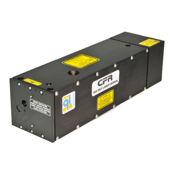
Laser Head
450
ICE
Power Supply
Coolant Lines* and Electrical Cables
Fill Bottle and Vent Tube
2
CABLE CONNECTION
1. Attach coolant lines to the back
of the laser head and back of the power
supply:
blue to blue
and
red to
2. Attach the double-connector side of the
electrical cable to the laser head. These
connectors have red dots indicating proper
orientation. Note: It is easier to attach
the bottom connector first. Ensure that the
connectors are fully seated. Note: You
should hear a "click".
3. Attach the other end of the D-Connector
to the back of the power supply and
tighten the thumb screws completely to avoid connector contact damage.
Note: Never operate the laser system without the connectors of the electrical
cable fully inserted and the thumbscrews tightened.
∗
If you received a DI Cartridge that is not attached to the coolant lines,
instructions to attach the DI Cartridge are on the opposite side of
this Quick Start Guide.
4. Attach the remote box to the remote box interface on the front of the
power supply. Thread the silver collar on the connector until it is flush
with the front of the power supply.
5. Connect the power cord to the back of the power supply.
6. Remove the white plastic shipping cover from the front of the laser head.
Do not discard.
CFR Laser Head/Standard ICE
WARNING
: OPERATING YOUR LASER WITHOUT COOLANT WILL CAUSE CATASTROPHIC FAILURE.
Accessory Kit (including keys)
Power Cord
Coolant (Distilled Water)
Electrical Cables
red.
450
3
FILL
1. Connect the vent tube to the fitting on the front of the reservoir
bottle.
2. Connect the vent tube to the reservoir vent port on the front of the
power supply.
3. Connect the fill bottle connector to the reservoir fill port on the front
of the power supply.
4. Add coolant to the fill bottle until water rises into the vent tube.
Remote Box Interface
Coolant Lines
Power Key Switch
Reservoir Vent Port
Minimum Coolant
Level Indicator
Reservoir Fill Port
DOC00076 Rev C
Power Supply
5. Insert the key into the power key switch and
turn it to the ON ("I") position.
6. Continue to add coolant until the coolant lines
are full and the coolant level is visible in the
vent tube (above the minimum coolant level
indicator). Note: The pink illuminated section
indicates the actual coolant level.
7. Disconnect the fill and vent tubes.
8. Secure laser head to the table using three 8-32
UNC screws.
Vent Tube Connector
(Connect to the ICE450 Vent Port)
Vent Tube Connector
(Connect to the Fill Bottle Connector)
(OVER)
(Connect to the ICE450 Fill Port)
Fill Bottle Connector
(Connect the vent tube here)
Fill Bottle Hose
Fill Bottle Connector
Advertisement

Related Manuals for Quantel CFR


Summary of Contents for Quantel CFR
- Page 1 Quick Start Guide For Your CFR Laser System CFR Laser Head/Standard ICE Power Supply WARNING : THIS IS A CLASS IV LASER. READ AND FOLLOW YOUR USER’S MANUAL BEFORE OPERATING TO AVOID DAMAGE OR PERSONAL INJURY. WARNING : OPERATING YOUR LASER WITHOUT COOLANT WILL CAUSE CATASTROPHIC FAILURE.
- Page 2 Quick Start Guide For Your CFR Laser System CFR Laser Head/Standard ICE Power Supply Your laser is pre-configured to operate at full energy START UP and Pulse Repetition Frequency (PRF). CONGRATULATIONS! The only routine maintenance required on the CFR Your system is ready for full operation.
Need help?
Do you have a question about the CFR and is the answer not in the manual?
Questions and answers