Honeywell MAXPRO NVR SE Quick Install Manual
Hide thumbs
Also See for MAXPRO NVR SE:
- Quick install manual (2 pages) ,
- Hardware installation and configuration manual (360 pages) ,
- Installation and configuration manual (358 pages)
Table of Contents
Advertisement
Quick Links
®
MAXPRO
NVR SE Quick Install Guide
Document 800-14458V4 – Rev A – 04/2014
Introduction
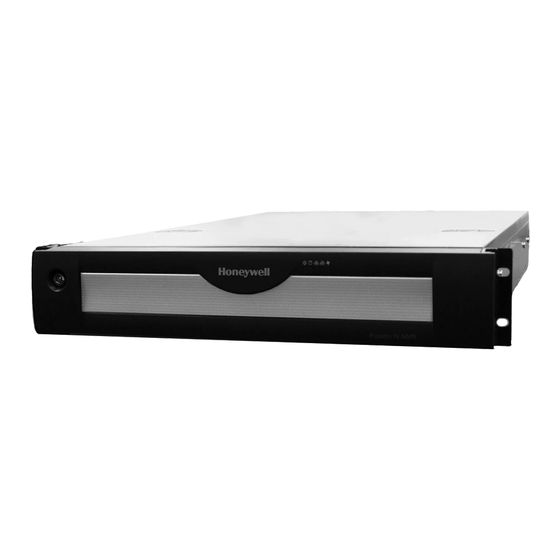
Welcome to your new Honeywell MAXPRO
installing your NVR, please read this guide carefully.
Unpack
Check that the items received match those listed on the order form and packing slip. The packing box should include, in
addition to your NVR unit and this guide:
Recovery DVD
MAXPRO NVR Client Software (Single Site) and Server
Software DVD (includes manuals)
MAXPRO Viewer Multi-Site Viewing Software Kit
(includes DVD and Getting Started Guide). Not shown.
Note
Other peripheral hardware (owner supplied) will also be needed for your installation (such as cameras, network
PoE switch for the camera network, network switch for a client workstation network, a monitor, and an optional
keyboard controller).
Install the Hardware
Mount the MAXPRO NVR SE Unit
Mount the MAXPRO NVR SE unit either on a flat surface or in a rack with the supplied
rail hardware kit. The kit allows the NVR to slide in and out of the rack it is mounted in and provides rear support for the
chassis. Refer to the installation instructions included with the rail hardware kit.
To remove the bezel from the front of the unit, turn the bezel key lock clockwise to loosen, then pull away from the unit.
To secure the front bezel, turn the bezel key lock counterclockwise.
Hard drive release button. The first
drive is the one on the top left.
Connect the Hardware
Rear Panel
2
DVI
1
3
Connect a local monitor to
one of the monitor outputs.
#
Connector
Connects to...
1
AC Power
Electrical outlet
2
VGA Port
VGA monitor
3
DVI-D Port
DVI monitor
4
Display Port
DP monitor
5
HDMI Port
HDMI monitor
6
LAN1 - Camera Network Port
Network
7
USB Ports (x4)
Various devices
8
LAN2 - Client Network Port
Network
9
S/PDIF (Optical)
10-14
Audio inputs and outputs
Not used
®
NVR SE.
This guide helps you set up the NVR right out of the box. Before
1
2
Not shown: HDMI to DVI adapter
Rail hardware kit (includes manual)
1
2
MAXPRO
®
NVR SE
Connect up to 32 IP cameras to a camera
network PoE switch and the switch to the
LAN1 camera network port.
10–14
6
8
4
Display Port
HDMI
5
7
9
Connect supplied keyboard
and mouse before powering
up the NVR.
Keyboard Controller (Optional)
included with your IP keyboard controller to connect it to the NVR.
Network Connections
cameras to the network PoE switch with CAT5 Ethernet cables. Optionally, connect the client workstation network port to
your client workstation network via a network switch. This allows remote access to your NVR. The default client workstation
network IP address must be changed to an available static IP address on your client workstation network.
Monitor(s)
connection of two monitors using any two of the outputs.
The recommended resolution for your monitor is 1280 x 1024 pixels (minimum 1024 x 768) and display colors of at least 32
bit.
Dual Network Configuration
MAXPRO
®
NVR SE
Local Monitor (not supplied)
USB
CAT5e
H4D2F1
HD4HDIH
Honeywell and Third-Party
IP Cameras
Contact your dealer to purchase Honeywell and third-party IP and analog cameras and encoder.
Power Up the Unit
Note
Honeywell recommends using an uninterruptible power supply (UPS) for the MAXPRO NVR SE unit, the camera
network switch, and the cameras to ensure that the NVR can continue to record video during a power outage. If you
need to monitor video during a power outage, consider a UPS for the monitor as well.
1.
Before powering up the NVR, turn on camera(s) and other devices — such as a network switch or router — connected
to the NVR.
2.
Press the power button on the front of the NVR.
Front Panel LEDs
3.
After powering up, you are prompted to log on. The Default user is user name: Administrator, password: Password1.
The user name and password are case sensitive.
The setup wizard starts automatically but may take two minutes. Proceed to
Follow the documentation that was
Connect a network PoE switch to the camera network port at the rear of the NVR. Connect your
The MAXPRO NVR SE comes with built-in graphics and four types of monitor outputs. The unit supports
HDMI Output
to HDMI monitor
DVI-D Output
to DVI monitor
VGA Output
to VGA monitor
Display Output
to DP monitor
®
MAXPRO
NVR SE
USB
VGA/DVI-D/HDMI/DP
Camera Network
Client Workstation
Network Port
Port (default
(default 172.25.254.101)
192.168.1.101)
Camera Network PoE Switch
Client Workstation Network Switch
CAT5e
CAT5e
CAT5e
CAT5e
CAT5e
CAT5e
HCD2F
HCD5HIH
Encoder
H3D2F1
HD3HDIH
Analog Cameras
System reset
Power button
Power LED (blue)
On = system powered up.
Mobile Devices
Router/
Firewall
Network
Wireless
Router
CAT5e
Client Workstation
Alarm mute
HDD activity
HDD Fan Fail LED (red)
LAN1, LAN2 LEDs
Off = not supported
Third Party Device
Configuration.
Document 800-14458V4 – Rev A –04/2014
Advertisement
Table of Contents

Related Manuals for Honeywell MAXPRO NVR SE


Summary of Contents for Honeywell MAXPRO NVR SE
- Page 1 Mount the MAXPRO NVR SE Unit Mount the MAXPRO NVR SE unit either on a flat surface or in a rack with the supplied rail hardware kit. The kit allows the NVR to slide in and out of the rack it is mounted in and provides rear support for the...
- Page 2 172.25.254.101 for LAN2 (Client Workstation Network) WATCH If more than one MAXPRO NVR SE unit is on the same network, you must assign a unique IP address and computer name to each unit (the default name is MAXPRO-NVR). Please wait while the system logs you on automatically as a Windows Logged-In User.
Need help?
Do you have a question about the MAXPRO NVR SE and is the answer not in the manual?
Questions and answers