Table of Contents
Advertisement
Quick Links
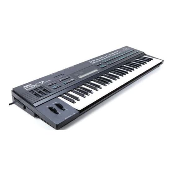
Yamaha DX7 8X EXPansion Installation
1: Introduction
The DX7_8X_EXP a powerful option board that provides increased memory and greater control
of the DX7.
THIS INSTALLATION WILL REQUIRE SOLDERING EXPERTISE AND ELECTRONIC
KNOWLEDGE. THE INSTALLATION SHOULD BE REFERRED TO A QUALIFIED
The soldering work entails direct wire connection to IC's already installed on a PCB. The
backup battery voltage is still live. This is a volatile Lithium battery. We accept no
responsibility for the work you perform on your DX7, your safety or material losses.
Precautions!
High Voltage Safety Warning
Unplug the audio cable. Turn the DX7 power switch OFF and disconnect the AC power cable
before opening the DX7.
ESD Precautions and Proper Handling Procedures
You should observe standard static-safe handling behavior when working with sensitive electronic
equipment such as synthesizers:
Avoid carpets in cool, dry areas.
o
Dissipate static electricity before handling any system components by touching a
o
grounded metal object.
If possible, use anti-static devices, such as wrist straps and floor mats.
o
Take care when installing the board. A damaged pin can render the board unusable.
o
Prevent damage to the connectors by aligning connector pins before you apply pressure.
o
A damaged pin can render the board unusable and can cause damage to system
components at power-on.
If disconnecting a cable, always pull on the cable connector, not on the cable itself.
o
Tools Required
Standard Philips screwdriver.
o
Standard flat-head screwdriver (small).
o
Standard soldering iron and solder. Because most soldering irons are grounded-tip,
o
you must unplug all cables from the DX7.
DX7_8X_EXP
TECHNICIAN.
Page 1 of 6
www.musictechnologiesgroup.com
Install v2.22
Preliminary
Advertisement
Table of Contents

Related Manuals for Yamaha DX7 8X EXP


Summary of Contents for Yamaha DX7 8X EXP
- Page 1 Yamaha DX7 8X EXPansion Installation 1: Introduction The DX7_8X_EXP a powerful option board that provides increased memory and greater control of the DX7. THIS INSTALLATION WILL REQUIRE SOLDERING EXPERTISE AND ELECTRONIC KNOWLEDGE. THE INSTALLATION SHOULD BE REFERRED TO A QUALIFIED TECHNICIAN.
- Page 2 Condition of DX7 While the DX7_8X_EXP will replace the functionality of damaged or missing EPROM and/or SRAM chips, it will not correct other problems your vintage synthesizer may have. It is recommended that the synth be in otherwise good condition before beginning the installation. For instance, the battery voltage should be checked and the battery replaced/repaired by a tech if necessary.
- Page 3 Loosen the 3 internal screws at the extreme right and left ends that hold the keybed in place. It is not necessary to extract them from the holes they reside in. Carefully lift the keybed slightly up and out (toward yourself) an inch or so.. You don't need to move it much.
- Page 4 Remove the EPROM and SRAM ICs The next step is to remove the EPROM and two SRAM ICs. The EPROM is found in location IC14 and the two M5M5118P SRAM chips are located at IC21 and IC20. Remove them prying slowly at each end of the chip back-and-forth with a small flat-head screwdriver.
- Page 5 Install the DX7_8X_EXP Printed Circuit Board Remove the DX7_8X_EXP board from the anti-static foam. Inspect the bottom of the board to make sure none of the pins have been damaged. You should see one collection of 28 pins (2 parallel strips of 14 pins), and a strip of 7 pins. Do NOT connect the cable to the board yet.
- Page 6 You will need to set the initial DX7_8X_EXP parameters on FUNCTION 13 (or 12) and then load up to 8 banks of 32 patches (what Yamaha calls Voices). Each bank must be activated by a patch selection (which will initially be garbled data) then the data can be loaded via cartridge or MIDI.
Need help?
Do you have a question about the DX7 8X EXP and is the answer not in the manual?
Questions and answers