Table of Contents
Advertisement
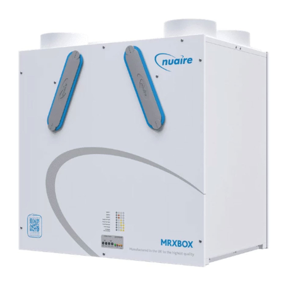
1.0 Introduction
The WM1 wall mounted range of units is designed to provide
mechanical supply and extract ventilation with heat recovery.
The unit is fitted with two independent fans. Each fan has full speed
control for background and boost ventilation rates.
To recover heat from the extract air the heat exchanger block is
utilised. The heat exchanger can recover up to 95% of the normally
wasted heat.
If the unit has integral automatic summer bypass (AB models
only) The bypass damper shall open automatically via a wax
actuator allowing the air to bypass the heat exchanger to deliver
fresh filtered air during the warmer months.
Figure 1. Airflow through unit (Standard unit).
Exhaust air
from house
to outside
Figure 2. Airflow through OH unit (Opposite hand unit).
Supply air
to house
2.0 Installation
Installation must be carried out by competent personnel in
accordance with the appropriate authority and conforming
to all statutory governing regulations. All mains wiring must be in
accordance with the current I.E.E. Regulations, or the appropriate
standards. Ensure that the mains supply (Voltage, Frequency and
Phase) complies with the rating label.
Please note a clear working space is required around the installed
unit to allow the cover to be removed and provide sufficient access
for maintenance such as filter change.
Please allow a minimum of 280mm in front of the unit.
Installation and Maintenance
MRXBOX95-WM1 (Standard Unit)
MRXBOX95-WM1-OH (Opposite hand Unit)
MRXBOX95AB-WM1 (Standard Unit)
MRXBOX95AB-WM1-OH (Opposite hand Unit)
Mechanical Ventilation Units with Heat Recovery for Wall Mounting
Intake air
from outside
Supply air
to house
Extract air
from house
Extract air
from house
Exhaust air
from house
to outside
Intake air
from outside
Nuaire Limited Western Industrial Estate Caerphilly United Kingdom CF83 1NA
T: 029 2085 8400 F: 029 2085 8444 E: info@nuaire.co.uk W: www.nuaire.co.uk
The unit must remain switched on at all times to maintain
ventilation within the dwelling. Turning the unit off will cause
long term damage to the unit and building fabric.
This appliance is not intended for use by persons (including
children) with reduced physical, sensory or mental capabilities,
or lack of experience and knowledge, unless they have been
given supervision or instruction concerning the use of the
appliance by a person for their safety. Children should be
supervised so that they do not play with the appliance.
The fan must be installed indoors, on a suitable wall away from
direct sources of frost, heat, water spray or moisture generation.
For a vibration-free result the unit must be mounted to a solid wall.
2.1 Wall Mounting the MVHR Unit
The unit is designed for wall mounting, only on a solid wall.
A gypsum block or stud/plasterboard wall will not suffice.
1. One part of the mounting bracket (supplied) should be offered up
to the wall, ensuring it's located horizontally. Mark the fixing points
through the pre drilled holes in the bracket and install with screws
(by others), ensuring the interlock side is at the top, (fig. 3).
Figure 3. Fixing the mounting bracket to the wall.
2. Install the unit on the wall by ensuring the bracket fixed to the
rear of the unit interlocks over the wall mounted bracket (fig. 4).
Figure 4. Mounting the unit on the wall mounted bracket.
Note: Care must be taken to ensure the unit is installed true in
all 3 dimensions. Failure to do so may result in overflow from the
internal condensation drip tray.
(See overleaf for wall mounting option details).
Note: the unit is not recommended for loft mounting.
1
The EMC Directive
2014/30/EU
The Low Voltage
Directive
2014/35/EU
09. 06. 16. Leaflet Number 671684
Advertisement
Table of Contents

Related Manuals for Nuaire Group BPC MRXBOX95-WM1


Summary of Contents for Nuaire Group BPC MRXBOX95-WM1
- Page 1 Installation and Maintenance The EMC Directive 2014/30/EU MRXBOX95-WM1 (Standard Unit) The Low Voltage Directive MRXBOX95-WM1-OH (Opposite hand Unit) 2014/35/EU MRXBOX95AB-WM1 (Standard Unit) MRXBOX95AB-WM1-OH (Opposite hand Unit) Mechanical Ventilation Units with Heat Recovery for Wall Mounting 1.0 Introduction The WM1 wall mounted range of units is designed to provide The unit must remain switched on at all times to maintain mechanical supply and extract ventilation with heat recovery.
- Page 2 Installation and Maintenance The WM1 Wall Mounted Range of Units 2.2 Option 1: Wall Mounting The MVHR unit fixed to a solid wall construction using the mounting bracket provided. Figure 5. Typical example of a cupboard mounted unit (Standard unit) fixed to a block work wall. Ducting in the Valve in ceiling.
-
Page 3: Condensate Drain
Installation and Maintenance The WM1 Wall Mounted Range of Units If used the flexible ducting must be kept to a minimum and should 2.3 Condensate Drain always be pulled taut. A maximum of 300mm should be used on each 1. The condensate must be discharged under a water level in a leg. - Page 4 Installation and Maintenance The WM1 Wall Mounted Range of Units Step 3: The required airflow rates are as follows: 2.7 ADF 2010 Ventilation Calculations the maximum whole dwelling extract ventilation rate (e.g. boost) Design of MVHR Systems should be at least the greater of step 1 and step 2. The MVHR system has been sized for the winter period.
- Page 5 Installation and Maintenance The WM1 Wall Mounted Range of Units 4.0 Ducting Arrangements - Standard Configuration Figure 9a. Typical ducted arrangement for a wall mounted unit using circular ducting. Exhaust air from *Insulated kitchen/bathroom to extract duct. outside via louvre grille. Minimum distance as specified Top of ceiling void.
-
Page 6: Electrical Connection
Installation and Maintenance The WM1 Wall Mounted Range of Units Electrical details:- 5.0 Electrical Connection Voltage: 240V 1ph 50Hz Consumption: 75W - 0.6 Amp Fuse rating: 3 Amp For good EMC engineering practice, any sensor cables or switched live cables should not be placed within 50mm of NOTE This unit must be earthed. -
Page 7: Status Indication
Installation and Maintenance The WM1 Wall Mounted Range of Units 6.0 Commissioning 7.0 Status Indication The status of the unit is indicated by a series of LED’s on the front cover. The varients are listed below. The filters fitted inside the unit are protected with a plastic film. -
Page 8: Replacement Of Parts
Installation and Maintenance The WM1 Wall Mounted Range of Units 10.0 Replacement of Parts Should any component need replacing Nuaire keep extensive stocks for quick delivery. Ensure that the unit is electrically isolated, before carrying out any work. Note: The supply cable must be replaced by an electrically competent person. - Page 9 Standard Assessment Procedure 2005 – Appendix Q MVHR Installation Guide Installation Guide and Checklist Mechanical Ventilation with Heat Recovery (Version – 11 February 2011) The Electric Heating and Ventilation Association have developed this guidance and checklist document in partnership with the Residential Ventilation Association (a HEVAC association), BRE and EST.
-
Page 10: Section 1: Installation Guidance
Standard Assessment Procedure 2005 – Appendix Q MVHR Installation Guide Page 2 of 6 Introduction This document is to be used in support of the SAP Appendix Q scheme which provides tested performance values for MVHR products. Note that all checklist items must be answered YES in order for the SAP Appendix Q test figures to be used in ‘As built’... - Page 11 Standard Assessment Procedure 2005 – Appendix Q MVHR Installation Guide Page 3 of 6 Figure 1 Ductwork Visual Guide Source: Approved Document F (England & Wales) 2006 2. Unit Fixing Decision Yes, No or Has the heat recovery unit been effectively insulated? Note: If the unit is not pre-insulated then ensure additional insulation is installed around the unit to minimise heat loss Has the heat recovery unit been fixed to a stable element of the...
- Page 12 Standard Assessment Procedure 2005 – Appendix Q MVHR Installation Guide Page 4 of 6 Figure 2 Sample Mounting Positions 3. Electrical Connection Decision Yes, No or Has the rating label been verified to establish suitability for the installation strategy and whether an earth is required (e.g. voltage, class I or II product status)? Has a local isolator been provided to enable the unit to be isolated for maintenance purposes?
- Page 13 Standard Assessment Procedure 2005 – Appendix Q MVHR Installation Guide Page 5 of 6 1. System Balancing & Calibration Decision Yes, No or Has the air flow been checked using a proprietary device such as an anemometer (recommended)? Have the controls been set following a defined process? Refer to figure 3 flow diagram Have all distribution grilles been locked where possible to minimise unapproved occupant adjustment?
- Page 14 Standard Assessment Procedure 2005 – Appendix Q MVHR Installation Guide Page 6 of 6 2. Handover and Control/Maintenance Advice Decision Yes, No or Has the customer been supplied with suitable documentation detailing maintenance and operational requirements? Has the customer been advised that opening windows is not recommended during normal use in order to ensure the energy efficient operation and performance of the balanced system? Has the customer been advised not to seal natural air flows from...
Need help?
Do you have a question about the BPC MRXBOX95-WM1 and is the answer not in the manual?
Questions and answers