Casio CFX-9970G Service Manual
Hide thumbs
Also See for CFX-9970G:
- User manual (474 pages) ,
- Manual (70 pages) ,
- Programming manual (47 pages)
Table of Contents
Advertisement
Quick Links
Advertisement
Table of Contents

Related Manuals for Casio CFX-9970G


Summary of Contents for Casio CFX-9970G
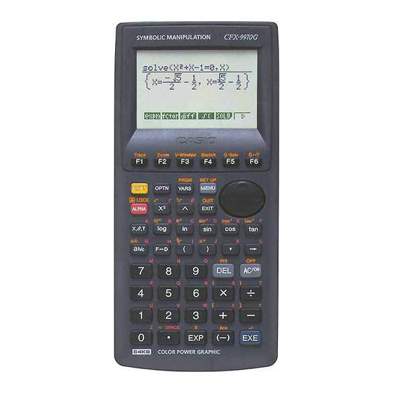
- Page 1 (without price) CFX-9970G (ZX-936A) AUG. 1997 CFX-9970G...
-
Page 2: Table Of Contents
CONTENTS SPECIFICATIONS ................... 3 GENERAL GUIDE 2-1. Modes ....................... 4 2-2. Color Contrast Adjustment ..............5 2-3. Power Supply ..................6 RESET OPERATION ..................9 DATA COMMUNICATIONS 4-1. Connecting Two Units ................10 4-2. Before Starting Data Communications ..........10 4-3. -
Page 3: Specifications
1. SPECIFICATIONS Variables: 28 Calculation range: ±1 × 10 to ±9.999999999 × 10 –99 and 0. Internal operations use 15-digit mantissa. (except in ALGBR Mode) Exponential display range: Norm1: –2 > [x], [x] > 10 (except in ALGBR Mode) Norm2: –9 >... -
Page 4: General Guide
2. GENERAL GUIDE 2-1. Modes • To select an icon 1. Press to display the Main Menu. MENU MENU 2. Use the cursor keys ( ) to move the highlighting to the icon you want. 3. Press to display the initial screen of the mode whose icon you selected. •... -
Page 5: Color Contrast Adjustment
Icon Mode Name Description TABLE Use this mode to store functions, to generate a numeric table of different solutions as the values assigned to variables in a function change, and to draw graphs. RECURsion Use this mode to store recursion formulas, to generate a numeric table of different solutions as the values assigned to variables in a function change, and to draw graphs. -
Page 6: Power Supply
• To adjust the color contrast 1. Use the cursor keys to move the pointer so it is next to CONTRAST. 2. Press the cursor key to make the display darker and the cursor key to make it lighter. Holding down either key changes the setting at high speed. - Page 7 • Be sure that the positive (+) and negative (-) poles of each battery are facing in the proper directions. • Never mix batteries of different types. • Never mix old batteries and new ones. • Never leave dead batteries in the battery compartment. •...
- Page 8 • Power supplied by memory back up battery while the main power supply batteries are removed for replacement retains memory contents. • Do not leave the unit without main power supply batteries loaded for long periods. Doing so can cause deletion of data stored in memory.
-
Page 9: Reset Operation
3. RESET OPERATION Warning! The procedure described here clears all memory contents. Never perform this operation unless you want to totally clear the memory of the calculator. If you need the data currently stored in memory, be sure to write it down somewhere before performing the RESET operation. -
Page 10: Data Communications
4. DATA COMMUNICATIONS 4-1. Connecting Two Units The following procedure describes how to connect two units with an optional SB-62 connecting cable for transfer of programs between them. To connect two units 1. Check to make sure that the power of both units is off. 2. -
Page 11: Performing Data Transfer Operation
4-3. Performing Data Transfer Operation Connect the two units and then perform the following procedures. Receiving unit To set up the calculator to receive data, press (RECV) while the data communication Main Menu is displayed. The calculator enters a data receive standby mode and waits for data to arrive. Actual data receive starts as soon as data is sent from the sending unit. - Page 12 Overwrite Password Data Item Contents Check* Check* Program Program contents Mat n Matrix memory (A to Z) contents List n List memory (1 to 6) contents File n List file memory (1 to 6) contents Y=Data Graph expressions, graph write/non-write status, View Window contents, zoom factors G-Mem n Graph memory (1 to 6) contents...
- Page 13 • To execute a send operation After selecting the data items to send, press (TRAN). A message appears to confirm that you want to execute the send operation. • {YES}..{sends data} • {NO}..{returns to data selection screen} Press (YES) to send the data. •...
-
Page 14: Data Communication Precautions
The following shows what the displays of the sending and receiving units look like after the data communication operation is complete. Sending Unit Receiving Unit Press to return to the data communication Main Menu. • Data can become corrupted, necessitating a RESET of the receiving unit, should the connecting cable become disconnected during data transfer. -
Page 15: Operation Check
5. OPERATION CHECK Performing this operation check, the data stored in this calculator is deleted. If you want not to delete these data, save these data to another CFX-9970G. STEP OPERATION DISPLAY NOTE Press button on the back of Reset... - Page 16 OPERATION DISPLAY NOTE STEP Press button. All blue dots are displayed Check for display Press button. Checkers are displayed Check for display Press button. Reverse checkers are displayed Check for display Press button. Check four colors. If the colors do not appear accurately, perform the adjust- ment mentioned in...
- Page 17 STEP OPERATION DISPLAY NOTE <<<ZX936 TEST MODE>>> TEST mode menu Press button. 4MbitROM 8MbitROM 1.Cnt 6.ROM 2.LCD 7.RAM 3.KEY 8.CYC 4.DET 9.3020 5.TRS 0.Rst Press button. RAMSIZE 128K byte RAM check The display shown RAMSIZE 128K byte to the left appears about 10 seconds RAMaddress later.
-
Page 18: To Save The Data
6. TO SAVE THE DATA CFX-9970G can transfer the customer's data to another CFX-9970G unit with memory protection only when replacing the LCD or the outer case. To connect the CSF Unit to another CSF Unit 1. Make sure that the power of both units are switched off. - Page 19 A unit B unit STEP NOTE OPERATION OPERATION OPERATION OPERATION Press button. 0.Self 0.Self Press button. 1.Send 1.Send 2.Receive 2.Receive Press button. WAITING ... Press button. SENDING ... RECEIVING ... COM END COM OK 0.Self Press button. 0.Self Press button. 1.Send 1.Send 2.Receive...
-
Page 20: Troubleshooting
7. TROUBLESHOOTING SYMPTOM CAUSE SOLUTION Clean or adjust pressure of Dirt or poor contact on battery Intermittent display contact Clean or replace power Poor contact on power switch switch Resolder or replace Poor connection on PC joiner Resolder Poor soldering on LSI, capacitor, or resistor Replace battery No display at all Weak battery... -
Page 21: Operation Problems
8. OPERATION PROBLEMS If you keep having problems when you are trying to perform operations, try the following before assuming that there is something wrong with the calculator. • Get the Calculator Back to its Original Mode Settings 1. In the Main Menu, select the RUN icon and press 2. -
Page 22: Error Message
9. ERROR MESSAGE Message Meaning Countermeasure Syn ERROR 1 Calculation formula contains an error. 1 Use to display the point where the error was generated and cor- rect it. 2 Formula in a program contains an error. 2 Use to display the point where the error was generated and then correct the program. - Page 23 Countermeasure Message MeaningMeaning •Simplify the formulas to keep stacks withi Stk ERROR • Execution of calculations that exceed the 10 levels for the numeric values and 26 capacity of the stack for numeric values or levels for the commands. stack for commands. •...
- Page 24 MeaningMeaning Message Countermeasure Undefined • No solution exists for the operation being • Change the input expression. performed in the ALGBR Mode. Overflow • The resulf of the operation being perform- • Change the input expression. ERROR ed in the AKGBR Mode exceds the range of the calculator.
-
Page 25: Schematic Diagrams
10. SCHEMATIC DIAGRAMS Main block-1 P button — 25 —... - Page 26 Main block-2 — 26 —...
- Page 27 Key block — 27 —...
- Page 28 Display drive block Sub ass'y Sub ass'y Contrast adj. — 28 —...
- Page 29 Memory block — 29 —...
-
Page 30: Parts List
11. PARTS LIST 12. EXPLODED VIEW(1/2) I t e m Code No. Parts Name Specification COMPONENTS 6421 0990 CASE/UPPER A140713-2 6420 7010 RUBBER/CONTACT A241013-1 6421 1000 HARD COVER A140715-2 6421 1010 COVER/BATTERY A241009-2 6421 1110 CASE/LOWER A140714-2 6419 9840 RUBBER/CONTACT A341594-1 6398 8740 SPRING/BATTERY A412218-1... - Page 31 12. EXPLODED VIEW(2/2) — 31 —...
- Page 32 8-11-10, Nishi-Shinjuku Shinjuku-ku, Tokyo 160, Japan Telephone: 03-3347-4926 MA0900171A Printed in Japan...
Need help?
Do you have a question about the CFX-9970G and is the answer not in the manual?
Questions and answers