Table of Contents
Advertisement
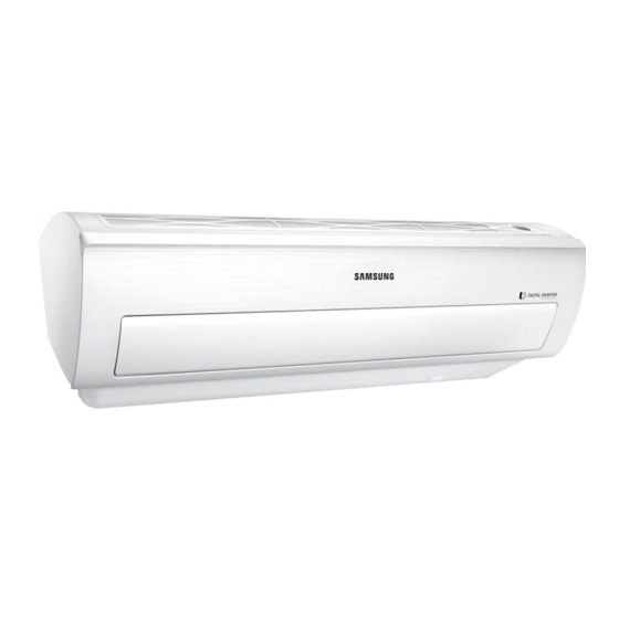
AIR CONDITIONER
AR09NXPDPWKNEE
AR12NXPDPWKNEE
AR09NXPDPWKXEE
AR12NXPDPWKXEE
SPLIT-TYPE AIR CONDITIONER
INDOOR UNIT
Model Code:
AR09NXPDPWKNEE
AR12NXPDPWKNEE
Basic Code:
AR09MSPDPWKNEE
AR12MSPDPWKNEE
CONTENTS
1.Precautions
2. Product
3. Alignment and Adjustments
4. Disassembly and Reassembly
5. Assy Control
6. Electrical Parts List
7. Wiring Diagram
8. Schematic Diagram
9. Operating Instructions
10. Troubleshooting
11. Block Diagram
12. Reference Sheet
OUTDOOR UNIT
AR09NXPDPWKXEE
AR12NXPDPWKXEE
AR09MSPDPWKXEE
AR12MSPDPWKXEE
ations
Advertisement
Table of Contents

Subscribe to Our Youtube Channel
Related Manuals for Samsung AR09NXPDPWKNEE


Summary of Contents for Samsung AR09NXPDPWKNEE
- Page 1 SPLIT-TYPE AIR CONDITIONER INDOOR UNIT OUTDOOR UNIT Model Code: AR09NXPDPWKNEE AR09NXPDPWKXEE AR12NXPDPWKNEE AR12NXPDPWKXEE Basic Code: AR09MSPDPWKNEE AR09MSPDPWKXEE AR12MSPDPWKNEE AR12MSPDPWKXEE AIR CONDITIONER CONTENTS 1.Precautions 2. Product ations 3. Alignment and Adjustments 4. Disassembly and Reassembly AR09NXPDPWKNEE AR12NXPDPWKNEE 5. Assy Control 6. Electrical Parts List 7.
- Page 2 6. Electrical Parts List ························································································ 6-1 6-1 INDOOR MAIN PCB ························································································ ·················· ·················· ··············· 6-2 OUTDOOR MAIN PBA······························································································································· · ······ 7. Wiring Diagram······························································································ 7-1 7-1 Indoor Unit············································································································ · · · · · ············································ 7-2 Outdoor Unit ·········································································································· · · · · · ········································· Samsung Electronics...
-
Page 3: Table Of Contents
12-3 Pressure & Capacity mark································································································ · · · ··························· 12-3 12-4 Q & A for Non-trouble··································································································· · · · ······························· 12-4 12-5 Cleaning /Filter Change································································································· · · · ····························· 12-7 12-6 Installation············································································································ · · · ············································ 12-9 12-7 Installation Diagram of Indoor Unit and Outdoor Unit···································································· 12-10 Samsung Electronics... - Page 5 Never store or load the air conditioner upside down or sideways to prevent the damage to the compressor. Young children or in rm persons should be always supervised when they use the air conditioner. Max current is measured according to IEC standard for safety. Current is measured according to ISO standard for energy e ciency. Samsung Electronics...
- Page 6 On those hot sweltering summer days and long restless nights, there is no better escape from the heat than the cool comforts of home. Your new air conditioner brings an end to exhausting hot summer days and lets you rest. Beat the heat with your own air conditioner this summer. Your new air conditioner not only provides maximum cooling power in the summer, but also can be an running cost.
- Page 7 COND Sub N.G.S N.G.S Refrigerant Refrigerant Control Unit Compressor Protection device(OLP) Air purifying system NEO TRIPLE FILTER NEO TRIPLE FILTER Cooling Operating Condition -15 ~ 46℃ -15 ~ 46℃ Heating Operating Condition -30 ~ 24℃ -30 ~ 24℃ Samsung Elctronic s...
- Page 8 Development Model Development Model AR09NXPDPWK/EE AR12NXPDPWK/EE Item Indoor Design Outdoor Net Weight Indoor(mm) 896*261*261 896*261*261 Outer Dimension (Width x Height x Depth ) Outdoor(mm) 790*548*285 790*548*285 Noise Air purifying system Filter Neo Triple Filter Neo Triple Filter Samsung Elctronic s...
- Page 9 DB90-07732A DB93-15883R 4301-000121 MANUAL USERS DB68-07961A MANUAL INSTALL DB68-07543A DB67-01533A...
- Page 13 1. Tack out the batteries of remote control. 2. Press the temperature button simultaneously and insert the battery again. 3. Make sure the remote control display shown as Step 2 Enter the Options Setup mode and select your options asscording to the following procedure. Samsung Electronics...
- Page 14 ’ ’ Ding’ ’ or ’ ’ Diriring’ ’ is heard and the OPERATION ICON( ) lamp of the display me time, then the input of option is completed. (If the deriving sound isn’t heard, try again pressing the ON/OFF button.) Samsung Electronics...
- Page 15 Every time you push the button, the display panel reads . . . repeatedly. Push the Mode button to set the display panerl to 1. Every time you push the button, the display panel reads . . . repeatedly. Samsung Electronics...
- Page 16 ■ Error mode 1. If all lam y to retry. orrect option code is set up for its model. 2. If the unit is not working properly or all lamps are continuously □ Option Items AR09NXPDPWKNEE 011045-196A66-271920-37133F 020000-100000-200001-300000 03433A-111E29-200000-300001 AR12NXPDPWKNEE 011045-176A88-272328-37153F...
-
Page 18: Indoor Unit
2) Detach FILTER PRE from the PANEL FRONT. 3) Cover Panel is assembled on bottom of indoor unit as shown in the figure. Remove the Cap Screw as shown on the right side and then remove the screw and separate the Cover Panel. Samsung Electronics... - Page 19 5) Separate the hook after pushing both end of Cover Panel as shown in the figure. (Watch out for the damage of the hook) 6) Raise front part upward obliquely as shown in the figure and then remove the hooks. Samsung Electronics...
- Page 20 Assembly of Cover Panel after service end. - Reassembly is in the reverse order of the removal. - Piping and drain hose must be careful not to damage and Progress must be done with both hands. Hook (Side) Hook (Center) Screw Cap Screw 4-10 Samsung Electronics...
- Page 21 4 HOOK Structures. When separate the hook : Use the (-) screw Driver. (-)Screw Driver Insert the hook and then pull the hook as shown on the right side. (Watch out for the damage of the hook) Samsung Electronics 4-11...
- Page 22 Parts Procedure Remark 9) Remove the Panel Frame from the Main Frame as shown on the right side. 10) Remove the WIFI KIT connector. WIFI KIT connector is located of Panel Front. (For model with WIFI KIT) 4-12 Samsung Electronics...
- Page 23 Caution : When y ou separate the connector, pull pressing the loc king button. 8) Loosen the Thermistor wire connector, Display wire connector. Caution : When you separate the connector, pull pressing the locking butt on. Samsung Electr onics 4- 13...
- Page 24 Caution: When you separate the connector, pull pressing the locking button. TRAY DRAIN 1) To detach TRAY-DRAIN from the main frame, pull the bottom of the TRAY-DRAIN towards you. 4-14 Samsung Electronics...
- Page 25 2) Unfasten the screw at the left side. (use + Screw Driver) 3) Unfasten the screw at the right side. (use + Screw Driver) 4) To detach Evaporator from the main frame, pull the bottom of the Evaporator towards you. Samsung Electronics 4-15...
- Page 26 FAN MOTOR 1) Unfasten the screw. (use + Screw Driver) & CROSS FAN 2) Detach the FAN Motor case. 3) Unfasten the screw a little. (use + Screw Driver) 4) Pull the CROSS-FAN to the left side. 4-16 Samsung Electronics...
- Page 27 4- 2 Outdoor Unit Detach the Cabinet Upper lik e the picture. 4-17...
- Page 28 5) Loosen 2 screw(CCW) on the right side of Cabinet Front. (Use +Screw Driver) 6) Loosen 2 screw(CCW) on the left side of Cabinet Front. (Use +Screw Driver) 7) Loosen 3 screw(CCW) on the front side of Cabinet Front. (Use +Screw Driver) 4-18...
- Page 29 4-19...
- Page 30 4-20...
- Page 31 1) Release 2 screw at CAP FAN 2) Release Nut at Fan Boss 3) Release 3 screws st Motor Brack et. 4) Detach Motor Wire from the Assy Control Out. 4-21...
- Page 32 4-3. EEPROM DOWNLOAD Normal 1) Power off 2) Take off the Cabinet : Check the LED off 3) Connect PC-Download Download Connector (10pin) Jig-PBA 4-13...
- Page 33 3) Connect PC-Download Jig-PBA Download Connector (10pin) 5) Execute the Universal EEPwriter program 5) CLICK 6) Select COM Port and connect 7) Open the file 8) Start Download 7) CLICK 8) CLICK 4-34...
- Page 34 Separate Case-WIFI Top BUTTON from Case-WIFI Button Detach SCREW SCREW from Case-WIFI Button Detach Assy Connector Wire from Case-WIFI Button WIRE *Caution When you separate the connector , pull press -ing the locking button Separate PBA WIFI from Case-WIFI Button Samsung Electronics...
- Page 35 ASSY CONNECTOR WIRE-DC SIGNAL DB93-15445A ASSY THERMISTOR IN DB95-05163A ASSY MODULE DB92-02861B ASSY PCB MAIN DB92-04101B ASSY CONNECTOR WIRE-DC SIGNAL DB93-14208A ASSY CONNECTOR WIRE-DISPLAY DB93-14209A ASSY CONNECTOR WIRE-DC SIGNAL DB93-14221A ASSY CONNECTOR WIRE-DC SIGNAL DB93-15445A ASSY THERMISTOR IN DB95-05163A Samsung Electronics...
- Page 36 ASSY CONNECTOR WIRE-AC SIGNAL DB93-16403A ASSY PCB SUB-HEATER DB93-13220A ASSY CONNECTOR WIRE-REACTOR DB93-15320A ASSY CONNECTOR WIRE DB93-09497E SCREW-TAPPING 6002-000630 HEAT SINK DB62-12196B ASSY-SCREW MACHINE DB91-00933A ASSY PCB INVERTER DB92-04025D ASSY PCB MAIN DB92-04029E ASSY CONNECTOR WIRE-DC SIGNAL DB93-07452B Samsung Electronics...
- Page 37 R803 R-CHIP 10Kohm,1%,1/10W,TP,1608 ..3 2007-000052 R804 R-CHIP 10Kohm,1%,1/10W,TP,1608 ..3 2007-000052 R816 R-CHIP 10Kohm,1%,1/10W,TP,1608 ..3 2007-000116 R825 R-CHIP 120ohm,5%,1/10W,TP,1608 ..3 2007-000143 R511 R-CHIP 4.7Kohm,5%,1/16W,TP,1005 ..3 2007-000143 R512 R-CHIP 4.7Kohm,5%,1/16W,TP,1005 ..3 2007-000143 R513 R-CHIP 4.7Kohm,5%,1/16W,TP,1005 ..3 2007-000143 R552 R-CHIP 4.7Kohm,5%,1/16W,TP,1005 Samsung Electronics...
- Page 38 R618 R-CHIP 12Kohm,1%,1/10W,TP,1608 ..3 2007-007306 R508 R-CHIP 100ohm,1%,1/16W,TP,1005 ..3 2007-007306 R515 R-CHIP 100ohm,1%,1/16W,TP,1005 ..3 2007-007306 R516 R-CHIP 100ohm,1%,1/16W,TP,1005 ..3 2007-007306 R517 R-CHIP 100ohm,1%,1/16W,TP,1005 ..3 2007-007306 R518 R-CHIP 100ohm,1%,1/16W,TP,1005 ..3 2007-007306 R519 R-CHIP 100ohm,1%,1/16W,TP,1005 ..3 2007-007306 R520 R-CHIP 100ohm,1%,1/16W,TP,1005 Samsung Electronics...
- Page 39 ..3 2402-001145 C701 C-AL,SMD 47uF,20%,50V,GP,TP,6.3X7.7mm ..3 2402-001145 C703 C-AL,SMD 47uF,20%,50V,GP,TP,6.3X7.7mm ..3 2802-001211 X501 RESONATOR-CERAMIC 8MHz,0.5%,TP,3.2x1.3x0.9 mm ..3 DB41-01362A PCB MAIN PCB MAIN FR-4,2Layer,T1.6,120*98,4,WIND FREE, A-STD#4, BLDC MOTOR ..3 DB91-01934A IC04 ASSY MICOM 18K_RAC_Windfree_Inv,STM-1750-OA,HART-m310,100MQFP ..4 0903-001864 IC04 IC-MICROCONTROLLER HART-M310,QFP,100P,20x14mm,8MHz,5V,600mW,-40to+85C Samsung Electronics...
- Page 40 R-CHIP 10Kohm,5%,1/16W,TP,1005 ..4 2007-000148 R-CHIP 10Kohm,5%,1/16W,TP,1005 ..4 2007-000148 R-CHIP 10Kohm,5%,1/16W,TP,1005 ..4 2007-000148 R-CHIP 10Kohm,5%,1/16W,TP,1005 ..4 2007-000148 R-CHIP 10Kohm,5%,1/16W,TP,1005 ..4 2007-000148 R-CHIP 10Kohm,5%,1/16W,TP,1005 ..4 2007-000148 R-CHIP 10Kohm,5%,1/16W,TP,1005 ..4 2007-000148 R-CHIP 10Kohm,5%,1/16W,TP,1005 ..4 2007-000148 R-CHIP 10Kohm,5%,1/16W,TP,1005 ..4 2007-000148 R-CHIP 10Kohm,5%,1/16W,TP,1005 Samsung Electronics...
- Page 41 R-CHIP 100ohm,1%,1/16W,TP,1005 ..4 2007-007306 R-CHIP 100ohm,1%,1/16W,TP,1005 ..4 2007-007306 R-CHIP 100ohm,1%,1/16W,TP,1005 ..4 2007-007306 R-CHIP 100ohm,1%,1/16W,TP,1005 ..4 2007-007306 R-CHIP 100ohm,1%,1/16W,TP,1005 ..4 2007-007306 R-CHIP 100ohm,1%,1/16W,TP,1005 ..4 2007-007306 R-CHIP 100ohm,1%,1/16W,TP,1005 ..4 2007-007306 R-CHIP 100ohm,1%,1/16W,TP,1005 ..4 2007-007306 R-CHIP 100ohm,1%,1/16W,TP,1005 ..4 2007-007306 R-CHIP 100ohm,1%,1/16W,TP,1005 Samsung Electronics...
- Page 42 2203-007456 C-CER,CHIP 1000nF,10%,25V,X5R,TP,1005,T0.5 ..4 2203-007456 C-CER,CHIP 1000nF,10%,25V,X5R,TP,1005,T0.5 ..4 2203-007456 C-CER,CHIP 1000nF,10%,25V,X5R,TP,1005,T0.5 ..4 2203-007456 C-CER,CHIP 1000nF,10%,25V,X5R,TP,1005,T0.5 ..4 2203-007456 C-CER,CHIP 1000nF,10%,25V,X5R,TP,1005,T0.5 ..4 2802-001211 RESONATOR-CERAMIC 8MHz,0.5%,TP,3.2x1.3x0.9 mm ..4 DB41-01352A PCB MAIN FR-4,2Layer,T1.6,142*48.5,8,RAC_OUT_MAIN,1Oz,284*194 ..4 DB91-01949A ASSY MICOM 18K_RAC_PF23_SG_OUT_NORDIC,STM-1760-OA ..5 0903-001864 IC-MICROCONTROLLER HART-M310,QFP,100P,20x14mm,8MHz,5V,600mW Samsung Electronics...
- Page 43 DB68-04014A-10...
- Page 44 7-2 Outdoor Unit...
-
Page 47: Refrigerating Cycle Diagram
8-3 Refrigerating Cycle Diagram... - Page 48 8-4 Indoor Main PCB_DB92-04101B CN21 CN81 CN61 CN63 CN62 CN43 CN76 CN32 CN91 CN77 CN31 CN51 CN72 CN75 CN71 CN61/CN62/CN63 - CN71 - POWER IN CN81 - SPI CN51 - WI-FI MODULE ① ② ③ ④ STEP MOTOR #1,#3 : AC220~240V #1: SPI SIGNAL #1 : WIFI UART SIGNAL1 #2 : WIFI UART SIGNAL2...
- Page 49 8-5 Outdoor INVERTER PCB(DB92-04025D) CN75 - SMPS IN CN75 - SMPS IN CNP001 : POWER N CNP002 : POWER L CNP003 : POWER EARTH CNP052 : REACTOR OTOR CN75 - SMPS IN CN75 - SMPS IN CNP401 : COMP CN203 : INV DOWNLOAD CNP051 : REACTOR CNP361 : ECO-COMM #1 :...
-
Page 50: Outdoor Pcb
8-5 Outdoor PCB MAIN (DB92-04029E) CN75 - SMPS IN CN75 - SMPS IN CN230 : DOWNLOAD 2. CN271 : EEP CN301 : 4 CN261 : MAIN-INV COMM : Main PBA S/W Download #1 : F1 #1 : INV_TXD-MAIN_RXD #2 : F2 #2 : INV_RXD-MAIN_TXD #3 : 5V #4 : SGND... -
Page 51: Wire Connecting The Indoor Unit Terminal Blocks
If not, there exists a possibility of re which can be caused by electric heat in the connecting part. : Good Bad : Ring terminal is connected reversely Bad : Not clamped Screw Bad : In the gap between Ring terminal & Screw Bad : Unused Ring Terminal Samsung Electronics... - Page 52 9-1-1 01 Air intake 06 Wi-Fi module 02 Air filter 07 SPi(S-plasma Ion) Lamp 03 Air flow blade (up and down) 08 Display 04 Air flow blade (left and right) 09 Power button / Remote control receiver 05 Room temperature sensor 10 (Inside) SPi Display 01 Temperature indicator...
- Page 53 Outdoor Unit 9-1-2...
- Page 54 01 Set temperature indicator 02 Timer option indicator 03 Operation mode indicator 04 Options indicator 05 Low battery indicator 06 Transmit indicator 07 Fan speed indicator 08 Vertical air swing indicator 09 Horizontal air swing indicator 10 Settings indicator 11 Power button 12 Temperature button 13 Options button 14 Timer button...
-
Page 55: Troubleshooting
HEAT mode, and indoor fan and out- Indoor fan and outdoor fan stop operation door fan do not operate intermittently for within 20% intermittently in a HEAT mode. of the total heater operation. Samsung Electronics 10-1... -
Page 56: Communication Error
Is the power is normal? Exchange the PBA of no power unit (check the LED Lamp) Exchange the indoor unit PBA. Is the communication error occurred again? Terminate the service. Exchange the outdoor unit PBA. 10-2 Samsung Electronics... - Page 57 Is the connection of power cable supply power and measure the voltage of #1-#2 in and communication cable normal? the connector Exchange the indoor PBA Below 0.5V or Over 4.5V? Micom error or connector check Exchange the indoor PBA Samsung Electronics 10-3...
- Page 58 Is the connection of power cable supply power and measure the voltage of #3-#4 and communication cable normal? and #5-#6 in the connector Exchange the indoor PBA Below 0.5V or Over 4.5V? Micom error or connector check Exchange the indoor PBA 10-4 Samsung Electronics...
- Page 59 Is the connected louver wire? Does operation start when swing button of the Normal remote control unit pushed? Is the voltage changeable at the pin#2~#5 of CN61, Exchange the PBA CN62, CN63 (louver connector)? Up/Down louver motor is faulty. Samsung Electronics 10-5...
- Page 60 Is the voltage of CN72 Exchange the Indoor PBA #3-#5 and #3-#6 with in 1Vdc~15Vdc during the operation? PBA problem or Motor problem Change the PBA first and check the operation Exchange the Fan motor 10-6 Samsung Electronics...
- Page 61 Is the connection of power cable supply power and measure the voltage of and communication cable normal? "(#1-#2)” i n the connector Exchange the Outdoor PBA Below 0.5Vdc or Over 4.5Vdc? Micom error or connector check Exchange the Outdoor PBA Samsung Electronics 10-7...
- Page 62 Is the connection of power cable p ower and measure the voltage of "(#5-#6)" in the connector and communication cable normal? Exchange the Outdoor PBA Below 0.5Vdc or Over 4.5Vdc? Micom error or connector check Exchange the Outdoor PBA 10-8 Samsung Electronics...
- Page 63 Is the connection of power cable supply power and measure the voltage of "(#3-#4) "in the connector and communication cable normal? Exchange the Outdoor PBA Below 0.5Vdc or Over 4.5Vdc? Micom error or connector check Exchange the Outdoor PBA Samsung Electronics 10-9...
- Page 64 Restart after power o Is the discharge over temperature Terminate the service sensor error appeared again? Download the EEPROM data Is the discharge over temperature Terminate the service sensor error appeared again? Exchange the Outdoor PBA Exchanged the Compressor 10-10 Samsung Electronics...
- Page 65 Is the voltage of "CNP901" #1-#3 over 250Vdc power supply error check Is the voltage of "CNP901" #3-#5 and Exchange the Outdoor PBA #3-#6 with in 1Vdc~15Vdc during the operation? PBA problem or Motor problem rst and check the operation Exchange the Fan motor Samsung Electronics 10-11...
- Page 66 Is the connection of compressor wire is normal? Connect the comp wire normally Download the EEPROM data Is the restart error occurred again? Terminate the service Is the compressor body and interphase Exchange the Outdoor PBA resistance insulated? Exchange the compressor 10-12 Samsung Electronics...
- Page 67 Is the connection of compressor wire is normal? Connect the comp wire normally (PBA and Compressor) Is the restart error occurred again? Terminate the service Is the compressor body and Exchange the Outdoor PBA interphase resistance insulated? Exchange the compressor Samsung Electronics 10-13...
- Page 68 Connect the comp wire normally Is the O.C error occurred again? Terminate the service Is the condition of indoor/outdoor temperature Restart after returning to the normal load normal load? Is the O.C error Terminate the service occurred again? 10-14 Samsung Electronics...
- Page 69 Is the position of Correct the sensor position or temperature sensor and sensing exchange the sensor value normal? Is the compressor body and interphase resistance Exchange the Outdoor PBA insulated? Exchange the compressor Samsung Electronics 10-15...
- Page 70 Check the power input Normal range(280Vdc~320Vdc) Is the DC_link sensing voltage("R101") is normal in operation mode? Exchange the Outdoor PBA Normal range (0.2Vdc~4.8Vdc) Exchange the Outdoor PBA Is the reactor insulation damaged? Exchange the Reactor 10-16 Samsung Electronics...
- Page 71 Start the operation (cooling mode or heating mode) Is the DC_link sensing voltage("B") is normal in operation mode? Exchange the Outdoor PBA Normal range (0.2Vdc~4.8Vdc) Exchange the Outdoor PBA Is the reactor insulation damaged? Exchange the Reactor Samsung Electronics 10-17...
- Page 72 Is the the input voltage is nomal? Check the input power in the powercord. Normal range(180Vac ~ 270Vac) Rest Start the operation (cooling mode or heating mode) Is the DC_link voltage ("CE101,CE102,CE103") is normal in operation mode? Check the input power Normal range(280Vdc~320Vdc) 10-18 Samsung Electronics...
- Page 73 Is the DC_link sensing Exchange the Outdoor PBA voltage("R105")is normal in operation mode? Normal range (0.2Vdc~4.0Vdc) Exchange the Outdoor PBA Is the reactor insulation damaged? Exchange the Reactor Samsung Electronics 10-19...
- Page 74 Is the position of Correct the sensor position or temperature sensor and the sensing exchange the sensor value normal? Is the connection cable for the compressor and power Correct the cable connection terminal normal? Exchange the Outdoor PBA 10-20 Samsung Electronics...
- Page 75 3) Is there no short or open around "IC451" ? 2. Troubleshooting procedure Rest Is the PFC shunt and IPM Exchange the Outdoor PBA shunt resistance value correct? Is the current sensor error appeared again? Terminate the service Exchange the Outdoor PBA Samsung Electronics 10-21...
- Page 76 4) Is the cover assembly in control-box normal? 2. Troubleshooting procedure Restart after power off. Are there screws in PBA-heatsink? Fastening the screw (4 screws) Check the fan connection Is the fan operation normal? Change the Fan motor Exchange the Outdoor PBA 10-22 Samsung Electronics...
- Page 77 Is the Comp Vlimit error occurred again? Terminate the service Is the condition of indoor/outdoor temperature Restart after returning to the normal load normal load? Is the O.C error Terminate the occurred again? service Samsung Electronics 10-23...
- Page 78 Is the position of Correct the sensor position or temperature sensor and sensing exchange the sensor value normal? Is the compressor body and interphase resistance Exchange the Outdoor PBA insulated? Exchange the compressor 10-24 Samsung Electronics...
- Page 79 2. Troubleshooting procedure MODEL "A" DB92-02866A CN501 DB92-02867A CN202 power o and download EEPROM data (or. Insert the service EEPROM IC) Restart after power o Terminate the service Is the error appeared again? Exchange the Outdoor PBA Samsung Electronics 10-25...
- Page 80 * Heating mode * * Cooling mode * Is the outdoor temperature over 40 or Is the outdoor temperature under -7 under -30 ? The temperature condition is too poor to operate. Wait until temperature is changed 10-26 Samsung Electronics...
- Page 81 Terminate the service. Check the EEV valve operation. Is the EEV valve connection normal? Connect the EEV valve. Is the EEV valve is operation? Check the sound of EEV valve Change the EEV valve. after power on. Samsung Electronics 10-27...
- Page 82 Check the pipe crack. Is the pressure of refrigerant normal? Fill up the refrigerant. Exchange the Indoor PBA Exchange the Outdoor PBA 10-28 Samsung Electronics...
- Page 83 Exchange the Main PBA Restart after power o . Is the power normal? Check the power source. Is AC power is normal for SMPS? Exchange the Main PBA CN150 : 220Vac~240Vac Check SMPS wire connection Exchange the PBA Samsung Electronics 10-29...
- Page 84 MAIN 12V(CE175) : 11Vdc ~ 13Vdc Is the SMPS is normal? Exchange the SMPS PBA MAIN 18V(CE170) : 17Vdc ~19Vdc Is the SMPS is normal? Exchange the SMPS PBA MAIN 5V(CE174) : 4.5V ~ 5.5Vdc Exchange the PBA Samsung Electronics 10-30...
- Page 85 2) Check the battery in remote control 3) All the lights out and check again : Change electronic typed to a rescent light 4) Put the set in operation and check the voltage of display PBA 5) Replace the display PBA 10-31 Samsung Electronics...
- Page 86 Is the EEV valve is operation? Change the EEV valve. Check the sound of EEV valve after power on. Check the pipe crack. Is the pressure of refrigerant normal? Fill up the refrigerant. Exchange the Indoor PBA Exchange the Outdoor PBA Samsung Electronics 10-32...
- Page 87 - Discharge temperature and the indoor [Execute the troubleshooting] temperature measurements c Check the refrigerant leaks. that the di erence is more than 10 . Check the PCB Relay. - Fill up perfectly refrigerant after re-vacuum. Execute the related trouble- shooting. 10-33 Samsung Electronics...
- Page 88 10-2-31 Pre-inspection Notices 1. Check if you pulled out the AC power plug when you eliminate the PCB or front panel 2. Don't hold the PCB side not impose excessive force on it to eliminate the PCB 3. Don’t pull the lead wire but hold the whole housing to connect or disconnect a connector to the PCB 4.
- Page 89 10-2-34 Outdoor detailed inspection procedure procedure Inspection Method Cause . Over current Plug out and pull the PCB out of . AC part and pattern short of Indoor the control box 1) Is 1st fuse disconnected? Check the PCB fuse 2) Is indoor PBA faulty? .
- Page 90 10-3 10-36...
-
Page 93: Reference Sheet
Reference Sheet Index for Model Name Buyer (1) Model (4) Inverter type (7) Color (8) Product Indoor AR RAC HP, R410A WT Jungfrau White Pearl Outdoor HP, R32 WU Vivaldi White AC CAC GM PM Gray SN Urban silver WQ DA White (2) Capacity (5) Feature WK DA White... -
Page 94: Low Refrigerant Pressure Distribution
0.001341 0.10197 0.73756 4.1868 14.286 0.0056146 0.42693 3.088 1.163 0.27778 3.9683 0.0015596 0.11859 0.85778 0.29307 0.06999 0.252 3.9302x10 0.029885 0.21616 745.7 178.11 641.19 2,544.4 76.04 9.8067 2.3423 8.4322 33.462 0.013151 7.233 1.3558 0.32383 1.0658 4.6262 0.0018182 0.13826 Samsung Electronics 12-2... - Page 95 12-3 12-3...
- Page 96 12-4 12-4...
- Page 97 12-5...
- Page 98 12-6...
-
Page 99: Cleaning /Filter Change
12-5 Cleaning /Filter Change 12-5-1 Cleaning your Air Conditioner To get the best possible use out of your air conditioner, you must clean it regularly to remove the dust that accumulates on the air filter. Air ter There is a hole on the bottom right side of the ter. Put your nger in that hole to get a grip on the ter and slightly push it up to release the hooks from the bottom side. - Page 100 12-6 12-6-1 12-6-2 12-8...
- Page 101 12-7 12-7-1 12-9...
- Page 102 12-7-2 12-10...
- Page 103 12-7-3 POWER SUPPLY Working Voltage 176V ~ 264V Within a 3% Deviation from Each Voltage at the Main Terminal of Voltage Imbalance Outdoor Unit Starting Voltage Higher than 80% of the Rated Voltage 12-7-4 WORKING RANGE Cooling Heating Item Lower(℃) Upper(℃) Rated(℃) Item Lower(℃) Upper(℃) Rated(℃) Outdoor...
Need help?
Do you have a question about the AR09NXPDPWKNEE and is the answer not in the manual?
Questions and answers