
Related Manuals for ENEL 200TH

Summary of Contents for ENEL 200TH
- Page 1 ENel - WROCŁAW Sp. z o. o. DESIGN AND MANUFACTURE OF POWER ELECTRONIC DEVICES ENEL200TH INVERTER WELDING MACHINE USER MANUAL DEALER:...
- Page 2 1. INTRODUCTION This manual contains information that will allow to take full advantage of ENEL200TH welding machine operation values and enable its safe use. Before operating the product, be sure to read this manual. 2. APPLICATION ENEL200TH welding machine is a modern direct current source designed mainly for TIG welding and with coated electrodes (MMA) of all types (ER-, EA-, EB-, ES-, ...) with diameters from ∅1.6 to ∅4.0.
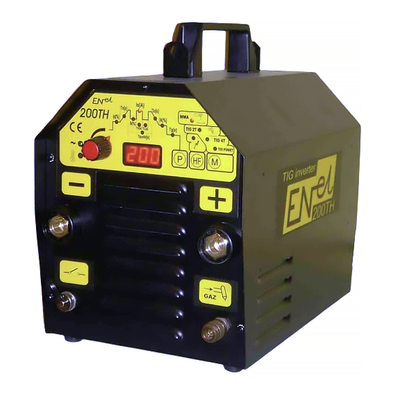
- Page 3 Figure1 The welder is equipped with a digital display (1), indicating the values of set parameters, a knob to adjust parameter values(2), operating mode switch (3), parameters switch (4), ignition mode switch (7) and light (8) indicating the selected ignition mode, 4 red lights indicating currently selected operation mode, 10 red lights indicating the currently adjusted parameter, green power supply indicator (5) and yellow light of device overheating indicator (6).
- Page 4 pressing the parameters switch button (4). It is indicated by blinking of the LED indicating welding current Is. Press again the button (4) to return to the operation with automatic open circuit voltage reduction. When the welding machine is equipped with a remote control module, it is possible to remotely change the welding current during performing the weld.
- Page 5 The welding process is initiated by pressing a control button on the grip. When the button is pressed the gas valve is opened. Releasing the button starts the ionizer - spark-over between an electrode and a workpiece should initiate ignition of the arc. If ignition of the arc does not occur within 2.5s ionizer is turned off and ignition process must be repeated.
- Page 6 • Ik[%] - final current adjustable as a percentage of the welding current Is within the range 5-50% with a resolution of 1%. • Tg[s] - time of gas flow after the arc extinction in seconds, adjustable in the range 1-25s with the resolution of 1s CONTACT IGNITION - LAMP (8) IS OFF The welding process is initiated by pressing (and releasing) a control button on the grip.
- Page 7 5) TIG PUNKT welding (spot welding) - the red light should indicate The following parameters can be set within given ranges: • Is[A] - welding current in amperes adjustable in the range of 5-200A with a resolution of 1A • Tn[s] - welding current rise time in seconds adjustable in the range 0.1-5s with a resolution of 0.1s •...
- Page 8 Entering three times of incorrect code disables the welding machine - unlocking is possible only in the ENEL service center. To enable the security function, follow these steps: ⇒...
- Page 9 To disable the security function, follow these steps: ⇒ When you turn the power on, press and hold the P and HF buttons until "HLP" symbol turns off (approx. 2 seconds) and you will see the firmware version number. After releasing the buttons you have to enter the correct PIN code.
-
Page 10: Technical Specifications
4. TECHNICAL SPECIFICATIONS Table 1 Item Parameter Unit Value Power supply (single-phase) 230V Frequency 50/60 Current adjustment range 5-170 Welding current: P50% P60% P100% Input current: P50% 25.5 P60% 22.8 P100% 19.2 Output Power: P50% P60% P100% Current adjustment range 5-200 Welding current: P40%... -
Page 11: Optional Accessory
5. OPTIONAL ACCESSORY (Can be supplied with rectifier for an extra fee) 1. 3m welding cable 1x25mm terminated with an electrode holder K-160. 2. 3m welding cable 1x25mm terminated with an electric clamp ZBK35. 3. Shoulder strap for carrying the rectifier. 4. - Page 12 Figure 2 General electric diagram...
-
Page 13: Connection To Power Mains
6. OPERATING INSTRUCTIONS 6.1 CONNECTION TO POWER MAINS 1. ENEL200TH welder is manufactured as a protection class I device and because of users safety should be connected only to the 3 phase electrical socket provided with the protective (earth) conductor. Electrical supply circuit should be protected with a time-delayed fuse rated at 20A or automatic circuit breaker, e.g. - Page 14 d) Connect the control cable of a TIG torch, equipped with the appropriate connector (C091 of Amphenol, Cat. No. T3300 001) to the socket on the front panel. Control wires connection diagram of the DUALTIG grip e) Select the method of arc ignition using button (7) - if the light (8) is off, contact ignition is selected, if it's off - selected is non-contact ignition.
-
Page 15: Tig Welding
3) Using button (3) select the welding with coated electrodes - the indicator should indicate the operation mode marked with MMA. At the same time a light indicating currently selected parameter - welding current Is - turns on. With the knob (2) Fig. 1 set the appropriate welding current. 4) Pressing button (4) select the operating mode with automatic open circuit voltage reduction (the LED indicating welding current Is illuminates continuously) or without automatic open circuit voltage reduction (the LED... -
Page 16: Ongoing Maintenance
CONTACT IGNITION - LAMP (8) IS OFF The welding process is initiated by pressing (and releasing) a control button on the grip. When the button is pressed the gas valve is opened. After releasing the button (while welding don't hold the button pressed!) you can ignite the arc by touching the workpiece and slightly lifting an electrode (the arc ignition occurs at the moment of lifting an electrode). -
Page 17: Fire, Explosion
8. REPAIRS Any repairs may be performed ONLY by persons authorized and trained by the manufacturer. 9. DANGERS DURING WELDING Prior to welding, authorized persons should thoroughly read this manual and strictly observe all given instructions. Non-compliance with these instructions may result in, among others, following dangerous consequences. -
Page 18: Electric Shock
9.4 ELECTRIC SHOCK Do not touch live electrical parts. Do not work in damp places and do not place the power supply on wet surfaces. Keep your clothing and body dry. Do not operate the rectifier without housing covers. Inspect the power cords, plugs and sockets, and the condition of the insulation of all current conducting wires and welding holders. -
Page 19: Spare Parts List
10. SPARE PARTS LIST Specification of main components is given in Table 2 Table 2 Item Description Pieces Handle Strap catch Thermal switch 80° C Thermal switch 70° C Bridge Rectifier Power transformer Control circuit IGBT transistor Capacitor 470 F/450V Electronic kit uP16v2 Electronic kit OPTOv2 Output socket...
Need help?
Do you have a question about the 200TH and is the answer not in the manual?
Questions and answers