Table of Contents
Advertisement
Advertisement
Table of Contents

Related Manuals for Asus STRIX B250G GAMING


Summary of Contents for Asus STRIX B250G GAMING
- Page 1 STRIX B250G GAMING...
- Page 2 Product warranty or service will not be extended if: (1) the product is repaired, modified or altered, unless such repair, modification of alteration is authorized in writing by ASUS; or (2) the serial number of the product is defaced or missing.
-
Page 3: Table Of Contents
Contents Safety information ....................... v About this guide ......................vi STRIX B250G GAMING specifications summary ..........viii Package contents ....................... xi Installation tools and components ................xii Chapter 1: Product Introduction Motherboard overview ................1-1 1.1.1 Before you proceed ..............1-1 1.1.2... - Page 4 3.6.11 USB Configuration ..............3-14 Monitor menu ................... 3-14 Boot menu ....................3-15 Tool menu ....................3-16 3.9.1 ASUS EZ Flash 3 Utility ............3-16 3.9.2 Secure Erase ................3-16 3.9.3 ASUS SPD Information ............. 3-17 3.9.4 Graphics Card Information ............3-17 3.10...
-
Page 5: Safety Information
Safety information Electrical safety • To prevent electrical shock hazard, disconnect the power cable from the electrical outlet before relocating the system. • When adding or removing devices to or from the system, ensure that the power cables for the devices are unplugged before the signal cables are connected. If possible, disconnect all power cables from the existing system before you add a device. -
Page 6: About This Guide
Refer to the following sources for additional information and for product and software updates. ASUS website The ASUS website (www.asus.com) provides updated information on ASUS hardware and software products. Optional documentation Your product package may include optional documentation, such as warranty flyers, that may have been added by your dealer. - Page 7 Conventions used in this guide To ensure that you perform certain tasks properly, take note of the following symbols used throughout this manual. DANGER/WARNING: Information to prevent injury to yourself when trying to complete a task. CAUTION: Information to prevent damage to the components when trying to complete a task.
-
Page 8: Strix B250G Gaming Specifications Summary
DDR4 ® 2133MHz. *** Refer to www.asus.com for the lastest Memory QVL(Qualified Vendors List). 1 x PCIe 3.0/2.0 x16 slot (at x 16 mode) Expansion slots 2 x PCIe 3.0/2.0 x1 slots... - Page 9 - Q-Slot - Q-DIMM ASUS Exclusive Features - Ai Charger - ASUS UEFI BIOS EZ Mode featuring friendly graphics user interface 1 x PS/2 keyboard/mouse combo port 1 x DVI-D port 1 x HDMI port 4 x USB 2.0 ports Rear Panel I/O 2 x USB 3.0 ports [blue]...
- Page 10 1 x Clear CMOS jumper (2-pin) 128 Mb Flash ROM, UEFI AMI BIOS, PnP, DMI3.0, WfM2.0, SM BIOS 3.0, ACPI 5.0, Multi-language BIOS, ASUS EZ Flash 3, CrashFree BIOS 3, F6 BIOS Features Qfan Control, F3 My Favorites, Last Modified log, F12 PrintScreen, and ASUS...
-
Page 11: Package Contents
Package contents Check your motherboard package for the following items. Motherboard STRIX B250G GAMING Cables 2 x SATA 6Gb/s cables 1 x I/O shield 1 x ROG cable label Accessories 1 x Strix series sticker 1 x M.2 screw package... -
Page 12: Installation Tools And Components
Installation tools and components Intel 1151 CPU ® Intel 1151 compatible CPU Fan ® Phillips (cross) screwdriver SATA hard disk drive PC chassis 1 bag of screws DIMM Power supply unit SATA optical disc drive (optional) Graphics card The tools and components listed above are not included in the motherboard package. -
Page 13: Chapter 1: Product Introduction
Unplug the power cord from the wall socket before touching any component. • Before handling components, use a grounded wrist strap or touch a safely grounded object or a metal object, such as the power supply case, to avoid damaging them due to static electricity. • Hold components by the edges to avoid touching the ICs on them. • Whenever you uninstall any component, place it on a grounded antistatic pad or in the bag that came with the component. • Before you install or remove any component, ensure that the ATX power supply is switched off or the power cord is detached from the power supply. Failure to do so may cause severe damage to the motherboard, peripherals, or components. ASUS STRIX B250G GAMING... -
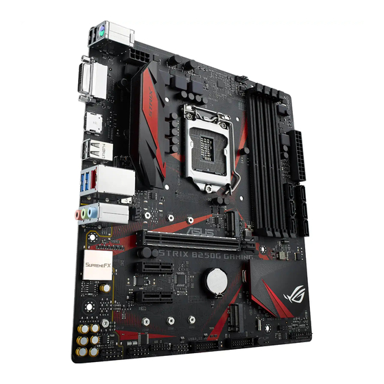
Page 14: Motherboard Layout
1.1.2 Motherboard layout 21.8cm(8.6in) CPU_FAN KBMS_USB910 DIGI +VRM EATX12V LGA1151 USB78 Intel I219V LAN_USB3_56 PCIE SATA IRST 2280 2260 2242 AUDIO CHA_FAN PCIEX16_1 S1220A PCIEX1_1 Super COVER Intel ® BATTERY B250 PCIEX1_2 PCIE SATA IRST 22110 2280 2260 2242 SB_PWR 128Mb BIOS USB3_12... -
Page 15: Central Processing Unit (Cpu)
15. SupremeFX LED 1.1.3 Central Processing Unit (CPU) The motherboard comes with a surface mount LGA1151 socket designed for the 7th / 6th Generation Intel Core™ i7 / Intel Core™ i5 / Intel Core™ i3, Pentium , and Celeron ® ® ® ® ® processors. STRIX B250G GAMING CPU socket LGA1151 • Ensure that all power cables are unplugged before installing the CPU. • Upon purchase of the motherboard, ensure that the PnP cap is on the socket and the socket contacts are not bent. Contact your retailer immediately if the PnP cap is missing, or if you see any damage to the PnP cap/socket contacts/motherboard components. • Keep the cap after installing the motherboard. ASUS will process Return Merchandise Authorization (RMA) requests only if the motherboard comes with the cap on the LGA1151 socket. • The product warranty does not cover damage to the socket contacts resulting from incorrect CPU installation/removal, or misplacement/loss/incorrect removal of the PnP cap. -
Page 16: System Memory
1.1.4 System memory The motherboard comes with four DDR4 (Double Data Rate 4) Quad Inline Memory Modules (DIMM) slots. A DDR4 module is notched differently from a DDR, DDR2, or DDR3 module. DO NOT install a DDR, DDR2, or DDR3 memory module to the DDR4 slot. STRIX B250G GAMING 288-pin DDR4 DIMM sockets Recommended memory configurations Chapter 1: Product Introduction... - Page 17 For more details, refer to the Microsoft support site at http://support.microsoft. ® com/kb/929605/en-us. • The design of the DIMM fan may vary. Ensure that the DIMM fan fits to the motherboard. • The default memory operation frequency is dependent on its Serial Presence Detect (SPD), which is the standard way of accessing information from a memory module. Under the default state, some memory modules for overclocking may operate at a lower frequency than the vendor-marked value. • For system stability, use a more efficient memory cooling system to support a full memory load (4 DIMMs) or overclocking condition. • Memory modules with memory frequency higher than 2133MHz and their corresponding timing or the loaded XMP profile is not the JEDEC memory standard. The stability and compatibility of the memory modules depend on the CPU’s capabilities and other installed devices. • Always install the DIMMS with the same CAS Latency. For an optimum compatibility, we recommend that you install memory modules of the same version or data code (D/C) from the same vendor. Check with the vendor to get the correct memory modules. • ASUS exclusively provides hyper DIMM support function. • Hyper DIMM support is subject to the physical characteristics of individual CPUs. Load the X.M.P. or D.O.C.P. settings in the BIOS for the hyper DIMM support. • Visit the ASUS website for the latest QVL. ASUS STRIX B250G GAMING...
-
Page 18: Expansion Slots
1.1.5 Expansion slots Unplug the power cord before adding or removing expansion cards. Failure to do so may cause you physical injury and damage motherboard components. PCIEX16_1 PCIEX1_1 PCIEX1_2 Slot No. Slot Description PCIe x16_1 slot PCIe x1_1 slot PCIe x1_2 slot Chapter 1: Product Introduction... -
Page 19: Headers
– – – Intel Lan i219V shared – – – ® 1.1.6 Headers Clear RTC RAM (2-pin CLRTC) This header allows you to clear the CMOS RTC RAM data of the system setup information such as date, time, and system passwords. CLRTC PIN 1 STRIX B250G GAMING Clear RTC RAM To erase the RTC RAM: Turn OFF the computer and unplug the power cord. Use a metal object such as a screwdriver to short the two pins. Plug the power cord and turn ON the computer. Hold down the <Del> key during the boot process and enter BIOS setup to re-enter data. If the steps above do not help, remove the onboard battery and short the two pins again to clear the CMOS RTC RAM data. After clearing the CMOS, reinstall the battery. ASUS STRIX B250G GAMING... -
Page 20: Onboard Leds
SB_PWR Standby Power Powered Off STRIX B250G GAMING Onboard LED SupremeFX LED The SupremeFX LED lights up in the following two ways to bring you an ultimate lighting effect. This LED also outlines the separation of the audio components from the rest of your motherboard. SupremeFX LED STRIX B250G GAMING SupremeFX LED Lighting Lit mode Description Breathing mode The LED blinks intermittently. Still mode The LED becomes solid red. You can turn off the SupremeFX LED or change the lit modes from the BIOS or the LED Control app in Ai Suite 3. To change the setting in BIOS, go to Advanced > Onboard Devices Configuration > SupremeFX LED Lighting item. See section 3.6.7 Onboard Devices Configuration for details. -
Page 21: Internal Connectors
Internal connectors Front panel audio connector (10-1 pin AAFP) This connector is for a chassis-mounted front panel audio I/O module that supports HD Audio. Connect one end of the front panel audio I/O module cable to this connector. AAFP HD-audio-compliant pin definition STRIX B250G GAMING Front panel audio connector We recommend that you connect a high-definition front panel audio module to this connector to avail of the motherboard’s high-definition audio capability. Serial port connector (10-1 pin COM) This connector is for a serial (COM) port. Connect the serial port module cable to this connector, then install the module to a slot opening at the back of the system chassis. PIN 1 STRIX B250G GAMING Serial port (COM) connector The COM module is purchased separately. - Page 22 USB 3.0 connectors (20-1 pin USB3_12, USB3_34) These connectors allow you to connect a USB 3.0 module for additional USB 3.0 front or rear panel ports. With an installed USB 3.0 module, you can enjoy all the benefits of USB 3.0 including faster data transfer speeds of up to 5 Gb/s, faster charging time for USB-chargeable devices, optimized power efficiency, and backward compatibility with USB 2.0. USB3_12 USB3_34 PIN 1 PIN 1 STRIX B250G GAMING USB3.0 front panel connectors The USB 3.0 module is purchased separately. USB 2.0 connector (10-1 pin USB1112) This connector is for a USB 2.0 port. Connect the USB module cable to this connector, then install the module to a slot opening at the back of the system chassis. This USB connector complies with USB 2.0 specification that supports up to 480 Mb/s connection speed. USB1112 PIN 1 STRIX B250G GAMING USB2.0 connector DO NOT connect a 1394 cable to the USB connectors. Doing so will damage the...
- Page 23 TPM connector (14-1 pin TPM) This connector supports a Trusted Platform Module (TPM) system, which securely stores keys, digital certificates, passwords and data. A TPM system also helps enhance network security, protect digital identities, and ensures platform integrity. PIN 1 STRIX B250G GAMING TPM connector The TPM module is purchased separately. CPU and chassis fan connectors (4-pin CPU_FAN, 4-pin CHA_FAN) Connect the fan cables to the fan connectors on the motherboard, ensuring that the black wire of each cable matches the ground pin of the connector. • DO NOT forget to connect the fan cables to the fan connectors. Insufficient air flow inside the system may damage the motherboard components.
- Page 24 +5 Volts Power OK -5 Volts +5 Volts PIN 1 +5 Volts PSON# +3 Volts -12 Volts +3 Volts +3 Volts PIN 1 STRIX B250G GAMING ATX power connectors • For a fully configured system, we recommend that you use a power supply unit (PSU) that complies with ATX 12 V Specification 2.0 (or later version) and provides a minimum power of 350 W. • DO NOT forget to connect the 8-pin EATX12V power plug. Otherwise, the system will not boot. • We recommend that you use a PSU with a higher power output when configuring a system with more power-consuming devices. The system may become unstable or may not boot up if the power is inadequate.
- Page 25 SPEAKER PWR_SW PIN 1 +HDD_LED- RESET +PWR_LED- * Requires an ATX power supply STRIX B250G GAMING System panel connector • System power LED (2-pin or 3-1 pin PWR LED) The 2-pin or 3-1 pin connector is for the system power LED. Connect the chassis power LED cable to this connector. The system power LED lights up when you turn on the system power, and blinks when the system is in sleep mode. • Hard disk drive activity LED (2-pin HDD LED) This 2-pin connector is for the HDD Activity LED. Connect the HDD Activity LED cable...
- Page 26 M.2 sockets (M.2_1~2) These sockets allow you to install M.2 SSD modules. M.2_1(SOCKET3) 2280 2260 2242 M.2_2(SOCKET3) 22110 2280 2260 2242 STRIX B250G GAMING M.2(SOCKET3) • M.2_1 socket supports SATA/ PCIe 3.0 x4 mode M Key design and type 2242/ 2260/ 2280 SATA/ PCIe 3.0 x4 storage devices. • M.2_2 socket supports PCIe 3.0 x4 M Key design and type 2242/ 2260/ 2280/ 22110 PCIe storage devices. • M.2_2 socket supports IRST (Intel Rapid Storage Technology). ® The M.2 SSD module is purchased separately.
-
Page 27: Chapter 2: Basic Installation
2.1.1 Motherboard installation Install the ASUS I/O Shield to the chassis rear I/O panel. Place the motherboard into the chassis, ensuring that its rear I/O ports are aligned to the chassis’ rear I/O panel. - Page 28 Place six (6) screws into the holes indicated by circles to secure the motherboard to the chassis. DO NOT overtighten the screws! Doing so can damage the motherboard. Chapter 2: Basic Installation...
-
Page 29: Cpu Installation
2.1.2 CPU installation Ensure that you install the correct CPU designed for LGA1151 socket only. DO NOT install a CPU designed for LGA1155 and LGA1156 sockets on the LGA1151 socket. ASUS STRIX B250G GAMING... -
Page 30: Cpu Heatsink And Fan Assembly Installation
2.1.3 CPU heatsink and fan assembly installation Apply the Thermal Interface Material to the CPU heatsink and CPU before you install the heatsink and fan, if necessary. To install the CPU heatsink and fan assembly Chapter 2: Basic Installation... - Page 31 To uninstall the CPU heatsink and fan assembly ASUS STRIX B250G GAMING...
-
Page 32: Dimm Installation
2.1.4 DIMM installation To remove a DIMM Chapter 2: Basic Installation... -
Page 33: Atx Power Connection
2.1.5 ATX power connection Ensure to connect the 8-pin power plug. ASUS STRIX B250G GAMING... -
Page 34: Sata Device Connection
2.1.6 SATA device connection Chapter 2: Basic Installation... -
Page 35: Front I/O Connector
2.1.7 Front I/O connector To install front panel connector To install USB 3.0 connector USB 3.0 To install USB 2.0 connector To install front panel audio connector AAFP USB 2.0 ASUS STRIX B250G GAMING... -
Page 36: Expansion Card Installation
2.1.8 Expansion card installation To install PCIe x16 cards To install PCIe x1 cards Chapter 2: Basic Installation 2-10... - Page 37 To install HYPER M.2 x4 card The SSD card is purchased separately. ASUS STRIX B250G GAMING 2-11...
-
Page 38: Installation
2.1.9 M.2 installation Chapter 2: Basic Installation 2-12... -
Page 39: Motherboard Rear And Audio Connections
Orange (Blinking Ready to wake up LAN port then steady) from S5 mode You can disable the LAN controllers in BIOS. Due to hardware design, the LAN1 port’s LEDs may continue to blink even when disabled. ASUS STRIX B250G GAMING 2-13... -
Page 40: Audio I/O Connections
** Audio 2.1, 4.1, 5.1, or 7.1-channel configuration Headset Port 4.1-channel 5.1-channel 7.1-channel 2.1-channel Light Blue (Rear Rear Speaker Rear Speaker Line In Rear Speaker Out panel) Front Speaker Front Speaker Front Speaker Lime (Rear panel) Line Out Pink (Rear panel) Mic In Mic In Bass/Center... - Page 41 Connect to 2.1 channel Speakers Connect to 4.1 channel Speakers Connect to 5.1 channel Speakers If you are using Windows 8.1/10 platform, use only the light blue audio port for Side ® Speaker Out in a 6-channel configuration. ASUS STRIX B250G GAMING 2-15...
-
Page 42: Starting Up For The First Time
Connect to 7.1 channel Speakers Starting up for the first time After making all the connections, replace the system case cover. Ensure that all switches are off. Connect the power cord to the power connector at the back of the system chassis. Connect the power cord to a power outlet that is equipped with a surge protector. -
Page 43: Turning Off The Computer
While the system is ON, press the power button for less than four seconds to put the system on sleep mode or soft-off mode, depending on the BIOS setting. Press the power switch for more than four seconds to let the system enter the soft-off mode regardless of the BIOS setting. ASUS STRIX B250G GAMING 2-17... - Page 44 Chapter 2: Basic Installation 2-18...
-
Page 45: Chapter 3: Bios Setup
BIOS Setup Knowing BIOS The new ASUS UEFI BIOS is a Unified Extensible Interface that complies with UEFI architecture, offering a user-friendly interface that goes beyond the traditional keyboard- only BIOS controls to enable a more flexible and convenient mouse input. You can easily navigate the new UEFI BIOS with the same smoothness as your operating system. -
Page 46: Bios Setup Program
RTC RAM via the Clear CMOS jumper. • The BIOS setup program does not support the Bluetooth devices. Please visit ASUS website for the detailed BIOS content manual. BIOS menu screen The BIOS Setup program can be used under two modes: EZ Mode and Advanced Mode. -
Page 47: Ez Mode
Click to go to Advanced mode Loads optimized Search on the FAQ default settings Click to display boot devices Selects the boot device priority The boot device options vary depending on the devices you installed to the system. ASUS STRIX B250G GAMING... -
Page 48: Advanced Mode
3.2.2 Advanced Mode The Advanced Mode provides advanced options for experienced end-users to configure the BIOS settings. The figure below shows an example of the Advanced Mode. Refer to the following sections for the detailed configurations. To switch from EZ Mode to Advanced Mode, click Advanced Mode(F7) or press the <F7> hotkey. - Page 49 Q-Fan Control(F6) This button above the menu bar displays the current settings of your fans. Use this button to manually tweak the fans to your desired settings. Refer to section 3.2.3 QFan Control for more information. ASUS STRIX B250G GAMING...
- Page 50 Move your mouse over this button to show a QR code, scan this QR code on your mobile device to connect to the BIOS FAQ web page of the ASUS support website. You can also scan the following QR code: Hot keys This button above the menu bar contains the navigation keys for the BIOS setup program.
-
Page 51: Qfan Control
Click to activate DC Mode configured PWM Mode Select a profile to Click to apply the fan setting apply to your fans Click to undo the Click to go back to main menu changes Select to manually configure your fans ASUS STRIX B250G GAMING... - Page 52 Configuring fans manually Select Manual from the list of profiles to manually configure your fans’ operating speed. Speed points Select to manually configure your fans To configure your fans: Select the fan that you want to configure and to view its current status. Click and drag the speed points to adjust the fans’...
-
Page 53: My Favorites
My Favorites is your personal space where you can easily save and access your favorite BIOS items. My Favorites comes with several performance, power saving, and fast boot related items by default. You can personalize this screen by adding or removing items. ASUS STRIX B250G GAMING... - Page 54 Adding items to My Favorites To add BIOS items: Press <F3> on your keyboard or click from the BIOS screen to open Setup Tree Map screen. On the Setup Tree Map screen, select the BIOS items that you want to save in My Favorites screen.
-
Page 55: Main Menu
Intel(R) SpeedStep(tm) [Auto] This item allows the operating system to dynamically adjust the processor voltage and cores frequency, resulting to a decreased average power consumption and decreased average heat production. Configuration options: [Auto] [Disabled] [Enabled] ASUS STRIX B250G GAMING 3-11... -
Page 56: Advanced Menu
Turbo Mode Parameters Long Duration Package Power Limit [Auto] Allows you to limit the Turbo Ratio’s time duration that exceeds the TDP (Thermal Design Power) for maximum performance. Use the <+> or <-> keys to adjust the value. The values range from 1 W to 4095 W. Package Power Time Window [Auto] Also known as Power Limit 1, this item allows you to maintain the time window for Turbo Ratio over TDP (Thermal Design Power). -
Page 57: System Agent (Sa) Configuration
This item allows you to use the Azalia High Definition Audio Controller. Configuration options: [Disabled] [Enabled] SupremeFX LED Lighting [Breathing Mode] Allows you to set the behavior of the audio LED. Configuration options: [Disabled] [Still Mode] [Breathing Mode] ASUS STRIX B250G GAMING 3-13... -
Page 58: Apm Configuration
M.2_1 Configuration [Auto] [Auto] Auto-detects the M.2 device mode. If a SATA device is detected, SATA6G_1 port will be disabled. [SATA mode] Supports M.2 SATA devices only. SATA6G_1 port will be disabled. [PCIE mode] Supports M.2 PCIe devices only. Intel LAN Controller [Enabled] [Enabled] Enables the Intel LAN controller. -
Page 59: Boot Menu
Allows you to select the type of network devices that you want to launch. Configuration options: [Ignore] [Legacy only] [UEFI driver first] Boot from Storage Devices [Legacy Only] Allows you to select the type of storage devices that you want to launch. Configuration options: [Ignore] [Legacy only] ASUS STRIX B250G GAMING 3-15... -
Page 60: Tool Menu
To launch Secure Erase, click Tool > Secure Erase on the Advanced mode menu. Check the ASUS support site for a full list of SSDs tested with Secure Erase. The drive may become unstable if you run Secure Erase on an incompatible SSD. -
Page 61: Asus Spd Information
Locked. SSDs might be locked if the Secure Erase process is either incomplete or was stopped. This may be due to a third party software that uses a different password defined by ASUS. You have to unlock the SSD in the software before proceeding with Secure Erase. -
Page 62: Exit Menu
® ASUS EZ Flash 3: Updates the BIOS using a USB flash drive. ASUS CrashFree BIOS 3: Restores the BIOS using the motherboard support DVD or a USB flash drive when the BIOS file fails or gets corrupted. 3.11.1... -
Page 63: Asus Ez Flash 3
3.11.2 ASUS EZ Flash 3 ASUS EZ Flash 3 allows you to download and update to the latest BIOS through the Internet without having to use a bootable floppy disk or an OS-based utility. Updating through the Internet varies per region and Internet conditions. Check your local Internet connection before updating through the Internet. - Page 64 To update the BIOS by Internet: Enter the Advanced Mode of the BIOS setup program. Go to the Tool menu to select ASUS EZ Flash Utility and press <Enter>. Select via Internet. Press the Left/Right arrow keys to select an Internet connection method, and then press <Enter>.
-
Page 65: Asus Crashfree Bios 3
The BIOS file in the motherboard support DVD may be older than the BIOS file published on the ASUS official website. If you want to use the newer BIOS file, download the file at https://www.asus.com/support/ and save it to a USB flash drive. - Page 66 Chapter 3: BIOS Setup 3-22...
-
Page 67: Appendix
Consult the dealer or an experienced radio/TV technician for help. The use of shielded cables for connection of the monitor to the graphics card is required to assure compliance with FCC regulations. Changes or modifications to this unit not expressly approved by the party responsible for compliance could void the user’s authority to operate this equipment. ASUS STRIX B250G GAMING... - Page 68 IC: Canadian Compliance Statement Complies with the Canadian ICES-003 Class B specifications. This device complies with RSS 210 of Industry Canada. This Class B device meets all the requirements of the Canadian interference-causing equipment regulations. This device complies with Industry Canada license exempt RSS standard(s). Operation is subject to the following two conditions: (1) this device may not cause interference, and (2) this device must accept any interference, including interference that may cause undesired operation of the device.
- Page 69 ASUS Recycling/Takeback Services ASUS recycling and takeback programs come from our commitment to the highest standards for protecting our environment. We believe in providing solutions for you to be able to responsibly recycle our products, batteries, other components as well as the packaging materials.
- Page 70 överensstämmelse finns på: www.asus.com/support Cijeli tekst EU izjave o sukladnosti dostupan je na: www.asus.com/support Українська ASUSTeK Computer Inc. заявляє, що цей пристрій відповідає Čeština Společnost ASUSTeK Computer Inc. tímto prohlašuje, že toto основним...
-
Page 71: Asus Contact Information
+1-510-739-3777 +1-510-608-4555 Web site http://www.asus.com/us/ Technical Support Support fax +1-812-284-0883 Telephone +1-812-282-2787 Online support http://qr.asus.com/techserv ASUS COMPUTER GmbH (Germany and Austria) Address Harkort Str. 21-23, 40880 Ratingen, Germany +49-2102-959931 Web site http://www.asus.com/de Online contact http://eu-rma.asus.com/sales Technical Support Telephone +49-2102-5789555 Support Fax... - Page 72 800 Corporate Way, Fremont Phone/Fax No: (510)739-3777/(510)608-4555 hereby declares that the product Product Name : Motherboard Model Number : STRIX B250G GAMING Conforms to the following specifications: FCC Part 15, Subpart B, Unintentional Radiators Supplementary Information: This device complies with part 15 of the FCC Rules. Operation is subject to the...
Need help?
Do you have a question about the STRIX B250G GAMING and is the answer not in the manual?
Questions and answers