Eiki LC-XNB4000N Service Manual
Hide thumbs
Also See for LC-XNB4000N:
- Owner's manual (109 pages) ,
- Brochure & specs (2 pages) ,
- Quick start manual (44 pages)

Related Manuals for Eiki LC-XNB4000N

Summary of Contents for Eiki LC-XNB4000N
-
Page 1: Revision History
LCD Projector Service Manual for EIKI LC-XNB4000N Ver. A_02 Date: 29 , May.’13... -
Page 2: Table Of Contents
Table of Contents Revision History......................2 Introduction .........................4 Important Service Information ..................4 Safety Notice ........................4 General Descriptions ....................4 Product Overview ......................5 Key Features……………………………………………………………………………………5 Packing ..........................6 Level 1 Alignment Service..................7 Software/Firmware Upgrade Process ................7 Update USB Firmware Procedure.................12 Disassembly/Assembly ....................16 Exploded Chart ......................17 Disassembly Indication ....................28 Level 2 Structure Diagram..................43 Block Diagram ......................44... -
Page 3: Introduction
Introduction This section contains general service information, please read through carefully. It should be stored for easy access place. Important Service Information Safety Notice Make sure your working environment is dry and clean, and meets all government safety requirements. Ensure that other persons are safe while you are servicing the product. DO NOT perform any action that may cause a hazard to the customer or make the product unsafe. -
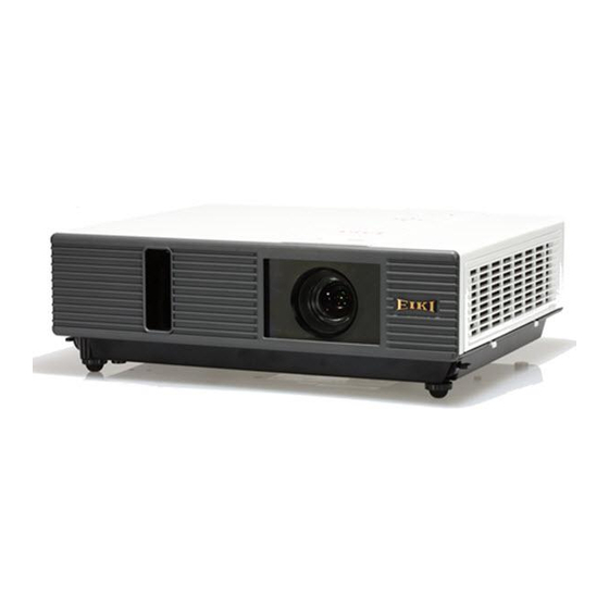
Page 4: Product Overview
Product Overview The Projector consists of the LCD projector controller, Lamp controller, Power supply system, and the system cooling controller. The LCD controller captures the digital PC data and video data and converts them into the LCD display device. The lamp controller controls the lamp’s power and synchronizes its frequency with color display sequence. -
Page 5: Packing
Packing... - Page 7 Download Firmware Procedure Make sure Power switch is turned to “OFF”. Plug power cord into projector. Plug in RS-232 cable between computer and projector side. 1. Please make sure your PC had already been installed ”Microsoft .NET Framework Version 2.0 ”.
- Page 8 3. Please make sure the ”Microsoft .NET Framework Version 2.0 ” had been installed completely, then, open the firmware folder. Execute the “ED_UpgradeFlasher.exe “(Picture 3) ( Picture 3 ) 4. After execute the “ED_UpgradeFlasher.exe “(Picture 3), you will see the window (Picture 4). Please press “Connect”...
- Page 9 5. After pressing “Connect” Button, please press “Flash Mode” Button as following Picture 5. ( Picture 5 ) 6. The Pixel Work Image Processor SDK Flasher Upgrader will process automatically. ( Picture 6)
- Page 10 7. When the firmware is flashed completely, you will see the below picture (Picture 7), please press “ OK ” to quit this program. ( Picture 7 ) 8. If you need to re-flash another projector, please repeat Item 4 to 7 steps.
-
Page 11: Update Usb Firmware Procedure
Update USB Firmware Procedure Connect the projector to an electrical outlet with the power cable. Connect RS232 cable from the computer to the projector's RS232C port. Connect mini-USB cable from the computer to the projector's mini USB port. 2. Launch “EDI_Serial_one.exe” 3. - Page 12 4. Go to [Flash: USB/ LAN Display] tab 5. Click “Flash mode” button 6. Clicked [Exit] 7. Launch the application program of “ActionsMPUpdate.exe 8. Wait for USB device “Actions USB Device” appeared.
- Page 13 9. Clicked [Update] Tab 10. focus Linux update item on Firmware button, then click and select the file where you put and need to update.
- Page 14 11. Clicked [Download] to update 12. Wait for download process ….. Done.
-
Page 15: Disassembly/Assembly
Disassembly / Assembly Content Exploded Chart - Top Cover - Main board / IO - Optical Engine - Power / Ballast Module - Exhaust Duct - Lamp - Inlet Duct - Lamp PSC Guide - Case Bottom - Lens Cover and CMOS Disassembly Indication - Top Cover - PCBA / Main board... -
Page 16: Exploded Chart
-Exploded Chart- Item Parent Name Parent Number ASSY_TOP_COVER MB ASM 23010317 ASSY_OPTICAL_ENGINE ASSY_POWER_BALLAST ASSY_EXHAUST_DUCT LAMP_ASSY 23040039 ASSY_INLET_DUCT ASSY_LAMP_DUCT and Fan ASSY_CASE_BOTTOM... - Page 17 -Exploded Chart- - TOP COVER - Item Part Name Part Number Q’ty ASSY_TOP_COVER Case Top+LED(GP) 13220623 Dress Plate-Case Top(GP) 13220650 Door-Lamp(GP) 13220277 Cover Filter-IR(GP) 13220282 IR Remote Cover (GP) 13220184 Inlet Door-Sponge Filter(GP) 13220278 Keypad(GP) 13220607 Front Ring(GP) 13220300 TOP Thermal Shield (GP) 13210121 Screw (GP) 13270074...
- Page 18 -Exploded Chart- - Main board / IO - Item Part Name Part Number Q’ty MB ASM 23010317 PCBA (GP) 23010314 Connect Plate (GP) 13210169 Plate-IO (GP) 13210168 Speaker_Line (GP) 13680010 Speaker Sponge (GP) 13340161 Aluminum Foil (GP) 13310045 COPPER_BOSS(GP) 13270005 SCREW(GP) 13270078 SCREW(GP)
- Page 19 -Exploded Chart- - Optical Engine - Item Part Name Part Number Q’ty ASSY_OPTICAL_ENGINE OE Main (CJ632DC)(GP) 13010034 Cover POP 1(GP) 13220293 LAMP_HOUSING_TOP(GP) 13220285 Lamp Housing BTM(GP) 13220284 Thermal Wire (GP) 13630015 Zoom Ring (GP) 13220295 Focus Ring(GP) 13220294 Sponge_lens (GP) 13340162 Cable -Ballast-Lamp (GP) 13660040...
- Page 20 -Exploded Chart- - Power/Ballast Module - Item Part Name Part Number Q’ty ASSY_POWER_BALLAST Case-Ballast(GP) 13210165 Mylar-Ballast(GP) 13290036 Ballast (GP) 13670054 Power Supply (GP) 13670049 Mylar-Power(GP) 13290035 Case-Power(GP) 13210104 Sponge PB Case(GP) 13340178 Aluminum Foil (GP) 13310040 IR PCBA (GP) 23010302 Washer (GP) 13330016 SCREW(GP)
- Page 21 -Exploded Chart- - Exhaust Duct - Item Part Name Part Number Q’ty ASSY_EXHAUST_DUCT Duct-Exhaust (GP) 13220290 Fan (GP) 13260026...
- Page 22 -Exploded Chart- - Lamp - Item Part Name Part Number Q’ty LAMP_ASSY 23040039 Concave_Fasten_Metal(GP) 13210101 Concave Lens (GP) 13070024 Holder-Lamp(GP) 13210124 Explosion mesh 0.8(GP) 13210123 Clip Lamp - Top (GP) 13210152 Clip Lamp - Bottom (GP) 13210153 Lamp Fin-Philips (GP) 13210154 Lamp (GP) 13080016...
- Page 23 -Exploded Chart- - Inlet Duct - Item Part Name Part Number Q’ty ASSY_INLET_DUCT Filter Inlet (GP) 13340152 Frame Sponge Filter(GP) 13220289 1+2= Filter Assy= 23390008(Filter Inlet+ Frame Sponge Filter) Filter Noise (GP) 13340149 Mesh (GP) 13210120 Inlet Duct 1(GP) 13220489 Aluminum Foil (GP) 13310032 Thermal Sensor (GP)
- Page 24 -Exploded Chart- - Lamp PSC Guide - Item Part Name Part Number Q’ty ASSY_LAMP_DUCT and Fan Duct1-Lamp(GP) 13220628 Duct2-Lamp(GP) 13220287 Inlet Blower-Lamp(GP) 13260027 SCREW(GP) 13270042 Fin of Duct (GP) 13210156...
- Page 25 -Exploded Chart- - Case Bottom -1 - See Next Page Item Part Name Part Number Q’ty ASSY_CASE_BOTTOM Case_BTM (GP) 13220491 Power Sponge (GP) 13340372 PCBA (GP) 23010149 AL Tape+ Mylar(GP) 13310018 Gasket (GP) 13290068 Aluminum Foil (GP) 13310042 Gasket (GP) 13290052 Gasket (GP) 13290069...
- Page 26 -Exploded Chart- - Case Bottom -2 - Item Part Name Part Number Q’ty ASSY_CASE_BOTTOM Inlet Blower-Panel(GP) 13260028 Sponge BB down(GP) 13340151 Sponge Gate(GP) 13340148...
-
Page 27: Disassembly Indication
- Disassembly Indication – -Top Cover Disassembly- a. Pull off the lamp cover b. Loose 2 screws and pull lamp module out c. Pull up the filter wall... - Page 28 d. Remove the wall e. Remove the filter case and filter sponge...
- Page 29 f. Remove 2 screws on the I/O board h. Turn to bottom side and remove 5 screws on the bottom case...
- Page 30 i. Remove the top cover j. Done...
- Page 31 - Disassembly Indication – -PBCA Disassembly- a. Remove the cable & wire b. Remove 6 screws on the PCBA module...
- Page 32 c. Remove the PCBA d. Done...
- Page 33 - Disassembly Indication – -Optical-Engine Disassembly- a. Remove 1 screw to remove the exhaust-fan module b. Remove the duct-cover...
- Page 34 c. Remove 2 screws to remove the lamp-blower d. Remove 5 screws which fixed the optical engine...
- Page 35 e. Remove the optical engine f. Remove one screw and cable...
- Page 36 g. Done...
- Page 37 - Disassembly Indication – -Power & Ballast module Disassembly- a. Remove 2 screws and remove the AC-filter b. Remove the cable which AC-filter to Power...
- Page 38 c. Remove 3 screws to remove the power-ballast module d. Done...
- Page 39 - Disassembly Indication – -Inlet duct module Disassembly- a. Remove the Aluminum tape b. Remove 3 screws of the air-duct and remove it...
- Page 40 c. Remove 4 screws of the panel-duct to remove the duct and blower d. Done...
- Page 41 - Disassembly Indication – -Other components Disassembly- a. Shielding, Mylar, sponge, aluminum tape and two gaskets, remove it directly b. Remove the security bar, lamp door switch and adjust-foots...
-
Page 42: Level 2 Structure Diagram
Level 2 Structure diagram The projector consists of the main board, keypad board, power PFC board, ballast board, door interlock switch, sensor board, thermal break sensor board and IR receiver board. Main Board is mainly composed of an image processor, EEPROM, flash memory, Thermal detective circuit, FANs driver circuit, temperature sensing circuit, Audio control circuit, LCD video signal processing generator, LCD panel driver circuit and low power management circuit. - Page 53 G. G. G. G.
-
Page 55: Level 3 Service Mode And Calibration
Level 3 Service Model and Calibration § Service mode (Hidden from end users) for Service Repair Center only. 1) Press button sequentially: POWER → AUTO → MENU (Please press as quickly as possible after start-up logo disappears.) KEYSTONE LEFT / RIGHT UP / DOWN VOL + / - INPUT... -
Page 56: Service Mode For Service Repair Only
Service mode & Calibration 2) You will see the image as below: a. Page: System Inf. b. Page: Set Up 01... - Page 57 Service mode & Calibration § Service mode: A. System Inf. A-1: Firmware Version: The firmware version which used at the projector. A-2: Build Date : Firmware build date A-3: Temp 1 : Temperature of inlet ventilation area A-4: Temp 2 : Temperature of projector panel A-5: Temp 3 : Temperature of projector lamp...
- Page 58 Service mode & Calibration § Service mode: B. Set Up 01 B-1: C&B Calibration : Contrast and Brightness calibration adjustment. B-2: Lamp Total Timer reset : Reset the lamp total time which is display on the first page of Engineering OSD. This timer will accumulate the total lamp time usage elapsed from shipping.
-
Page 59: Lamp Timer Reset
Service mode & Calibration C. Lamp Timer Reset: a. Select “ Lamp Timer Reset ” b. Press “ right key ” c. Confirmation information shows up as 〈fig 4〉 d. Select “ Yes ” e. Press “ right key ”... -
Page 60: Contrast And Brightness Calibration
Service mode & Calibration D. Contrast and Brightness Calibration a. Select pattern as 〈fig 7〉 <fig 7> b. Select OSD→Picture→ Display mode→Nature mode (as fig 8) <fig 8> c. Enter “ Service mode ” (Press POWER→AUTO→MENU on keypad) d. Select page “ System Inf. ” e. -
Page 61: Security
Service mode & Calibration - Security - PIN Lock Protect CAUTION: Once the PIN code had been set, the projector can’t be used unless you entered the correct PIN code. To avoid unnecessary trouble, if you activate the “PIN Lock Protection”, it is highly recommended that you write down the PIN code and keep it in a safe place. - Page 62 Service mode & Calibration - Security - Modify PIN lock protection Activate the OSD menu and go to SECURITY -> PIN lock protection Press Right button to change PIN lock protection mode IMPORTANT: To change the PIN lock protection state, you must enter the PIN code first.
- Page 63 Service mode & Calibration - Security – PIN key in operation When the projector is turned on and the PIN lock protection is set to “on”, the image will show as above. Enter PIN code by Keypad or Remote control. on keypad and on remote control mean If you wish to input “1”, press “...
- Page 64 Service mode & Calibration - Security – - PIN lock protection mechanism 1. PIN lock protection can be enabled through OSD setting. 2. If the PIN lock protection function is on, the system will display the PIN lock number entering screen after lamp is on. After user’s three times wrong PIN number input, system switches off the lamp.
- Page 65 Service mode & Calibration Security – 4. System should stores a random number array with 10000 elements for each customer. 5. This magic number is the nth element of the random number array and the n (PIN number) is generated as the remainder of 1000 divides the internal timer counter of Pixelworks scalar chip.
- Page 66 Service mode & Calibration - Security – § Auto Filter Alert The function is to remind user for filter cleaning or replacement. Filter counter setting Select from (100H/300H/500H) depending on the use environment. For clean environment, set the filter timer longer. For dirty environment, set the filter timer shorter.
-
Page 67: Electrical Interface Character
Electrical Interface Character Interface Definition -Input / Output Connector Specification - Analog RGB Input/output (1)Connections (15P HD-Sub) 5 5 5 5 4 4 4 4 3 3 3 3 2 2 2 2 1 1 1 1 9 9 9 9 8 8 8 8 7 7 7 7 6 6 6 6... - Page 68 (6)Composite Sync. TTL:Negative -Composite Video signal (1)Connections (2)Pin Number Define Pin2 Pin1 Pin NO Signal name Connection Video Signal (GND) Video Inputs (2)Connector:RCA jack (3)Input signal polarity: Composite signal , Sync:Negative (4)Input level:Video signal: 1.0V ±0.2V p-p 75Ω terminate, NRZ - S-Video signal (1)S-Video Connections and Connector (2)Pin Number Define...
- Page 69 -IR Code, RS232 Command, and factory menu 1. IR Code -IR Remote Control -IR Remote Control Specification Items Specification Projector Transceivers The projector shall have IR transceivers on the front and rear of the unit. Working Frequency 38k Hz or 57k Hz Effective Range and Distance 7 meters / Horizontal ±15°...
- Page 70 2. RS232 Command -RS232 Control -Communication Protocol Items Specification Standard Baud rate 9600 bps Data length 8 bits Parity None Stop bit 1 bit Flow Control None -RS232 Cable Define PC side Projector side with D-sub pin RX 2 RX 3 TX 3 TX 2 GND 5...
- Page 71 -Command List Command (HEX+CR) Function Remarks C00(43 30 30 0D)# POWER ON Used at standby mode only C01(43 30 31 0D) POWER OFF C02(43 30 32 0D) COMPUTER1 C04(43 30 34 0D) COMPUTER2 C03(43 30 33 0D) YPBPR No use in Boston series C05(43 30 35 0D) C06(43 30 36 0D) VIDEO...
- Page 72 C98(43 39 38 0D) KEYSTONE+ C99(43 39 39 0D) KEYSTONE- C51(43 35 31 0D) C52(43 35 32 0D) USB-UP For USB source only C53(43 35 33 0D) USB-DOWN For USB source only C54(43 35 34 0D) USB-LEFT For USB source only C55(43 35 35 0D) USB_RIGHT For USB source only...
- Page 73 *ACK (acknowledge) is 0x06 in hexadecimal *NAK (negative acknowledge) is 0x15 in hexadecimal *CR (carriage return) is 0x0D in hexadecimal. # At standby mode, only these commands can be accepted. (All the above commands are available at normal operation mode except the “POWER ON” command. *The temperature of Image temp sensor - Inlet temp sensor is greater than 18 degrees Celsius...
Need help?
Do you have a question about the LC-XNB4000N and is the answer not in the manual?
Questions and answers