Table of Contents
Advertisement
Quick Links
Advertisement
Table of Contents

Related Manuals for Aussie Fit V-450

Summary of Contents for Aussie Fit V-450
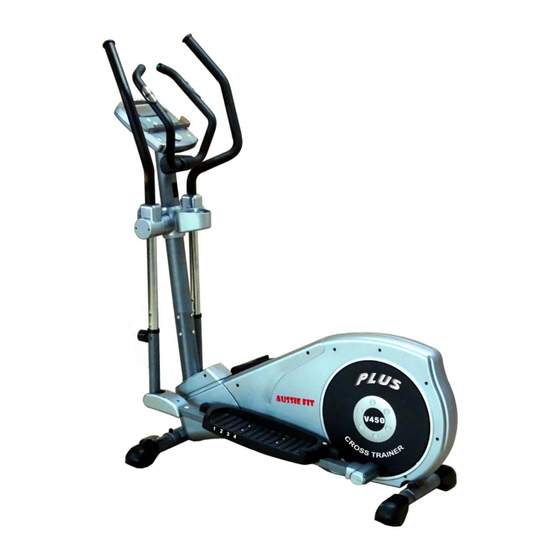
- Page 1 USER’S MANUAL V-450 Crosstrainer SERIAL NUMBER (found on frame):...
-
Page 2: Pre-Assembly
PREASSEMBLY For future service or related questions: Please staple your receipt and/or write in the name and phone number of the retail store where you purchased your item. Name: ______________________________ Phone Number: ___________________ Receipt: ______________________ Open the boxes: You are now ready to open the boxes of your new equipment. Make sure to inventory all of the parts that are included in the boxes. Check the Parts List for a full count of the number of parts included for this product to be assembled properly. -
Page 3: Power Requirements
POWER REQUIREMENTS Power Requirements: IMPROPER CONNECTION OF THE EQUIPMENT GROUNDING CONNECTOR CAN RESULT IN THE RISK OF AN ELECTRIC SHOCK. CHECK WITH A QUALIFIED ELECTRICIAN OR SERVICE MAN IF YOU ARE IN DOUBT AS TO WHETHER THE PRODUCT IS PROPERLY GROUNDED. DO NOT MODIFY THE PLUG PROVIDED WITH THE PRODUCT, IF IT WILL NOT FIT THE OUTLET;... - Page 4 SUPPLIED COMPONENTS Base Frame Console Upright Tube Bottle Holder Pedal (R/L) Pedal Support Tube (L) Pedal Support Tube (R) Rear Stabilizer Front Stabilizer Fixed Handlebar Swing Arm Handlebar (R) Hardware Swing Arm Handlebar (L) Rear Pedal Tube Cover Bottom (L/R) Rear Pedal Tube Cover Bottom (L/R) Upright Tube Front Cover Power pack...
- Page 5 MILLIMETERS TOOL included with machine: M8 socket Screw driver 5mm M8/M10 wrench General tools prepared by user: Screw driver 5mm M8 wrench M10 wrench...
- Page 6 Handlebar end cap Screw Handlebar grip Washer T-Bar grip Flywheel Hand pulse grip unit Speed Sensor Cable End cap Belt Screw End cap Locking washer Bearing Washer Pedal, LH Sleeve Pedal, RH Sleeve Adjustable foot Washer End cap Nylock nut End cap (T-Bar) Pedal tube shaft Middle cover, LH...
- Page 7 88(B) Lower cover Console cable 990MM Cable Cable 850MM Power wire 750MM Rear cover A for upright tube Front cover A for upright tube Inner cover for swivel tube Front cover for swivel tube Rear cover for swivel tube End cap End plug Screw Metal Spring plate...
- Page 9 STEP 1: Attach the Front Support (Front Stabilizer) ASSEMBLY NOTE: To make attaching the support easier place a large Styrofoam block under the machine. (A) Attach the front support to the base frame with the wheels facing outward. (B) Align the 2 bolt holes in the front support with the bolt holes in the main frame.
- Page 10 STEP 2: Attach the Rear Support (Rear Stabilizer) NOTE: To make attaching the support easier place a large Styrofoam block under the machine. (A) Attach the rear support to the base frame (B) Align the 2 bolt holes in the rear support with the bolt holes in the main frame.
- Page 11 STEP 3: Attach the Upright Tube Assembly to the Base Frame As photo shown A) place upright tube on top of a chair ( or by a second person to assist holding) close to the main frame be facilitated to connect the cables.
- Page 12 STEP 4: Attach the Pedal Tube Assembly...
- Page 13 STEP 5: Attach the Pedal Tube Assembly (A) Secure the pedal tube to the base frame crank arm by using 1 x #17 washer and 1 x #12 M10 lock nut. Completely tighten with a wrench (B) Attach and secure the Rear pedal tube covers #101 and #102 to the left pedal tube by using 4 x #29 screws.
- Page 14 STEP 6:Attach the Console Base and Handlebars...
- Page 15 STEP 7: Attach the Upper Swing Arm Assembly and Covers (A) Place the upper swing arms left and right #72/#73 in to the lower swing arms #69/#70 (B) Secure the upper and lower swing arms together by using 4 x #18 Allen bolts, 4 x #A spring washer and 4 x #65 washers.
- Page 16 STEP 8: Attach the Computer and Console Base Rear Cover # 61 # 88...
- Page 17 STEP 9: Attach the Computer and Console Base Rear Cover (A) connect cables comes out from console (#43) & cables from the upright tube together (B) set console (#43) to the top plate on the upright tube and secure both with for screws (E) Due to console/computer will assemble with a higher Location of machine SUGGEST to have a partner to Hold the computer and make sure all the Cable/plug Are plug in firmly or use a Chair...
- Page 18 STEP 10: Attach the Bottle Holder and Pedals Attach the rear cover #94 to the bottle holder #105and secure by using 4 x #104 screws. Place the front cover and the rear cover with the bottle holder attached around the upright tube and secure by using 4 x #29 screws (See Fig. 9A) Locate the left and right pedals.
- Page 19 STEP 11: Attach the Power Supply (A) Before plugging in the power supply verify the voltage specifications on the lable. (B) Plug the adaptor jack in to the inlet on the bottom rear of the elliptical. (C) Plug the power supply in to the wall outlet. V450...
- Page 20 Mp3, Fan and Procedure to Move the Equipment Mp3, Fan and Procedure to Move the Equipment Mp3 and iPod Usage To play music or audio books through the console sound system while you exercise, plug the included audio cable into the jack on the back of the console and into a jack on your MP3 or iPod; make sure that the audio cable is fully plugged in.
-
Page 21: Muscle Chart
MUSCLE CHART MUSCLE CHART Targeted muscle groups: The exercise routine that is performed on this product will develop primarily lower body muscle groups. These muscle groups are shown in gray color on the chart below. MUSCLE GROUPS Shoulder muscles Calf muscles Pectoral muscles Trapezius muscles Bicep muscle... -
Page 22: Stretching Routine
Warm up and cool down: STRETCHING ROUTINE A successful exercise program consists of a warm-up, aerobic exercise, and a cool-down. Do the entire program at least two and preferably three times a week, resting for a day between workouts. After several months, you can increase your workouts to four or five times per week. -
Page 23: Computer Operation
Toe Touch: Shoulder Lift: Slowly bend forward from your Lift your right shoulder up toward waist, letting your back your ear for one count. Then lift shoulders relax as you stretch your left shoulder up for one count toward your toes. Reach down as as you lower your right shoulder. - Page 24 COMPUTER OPERATION Console Display Description Display Display Range Setting Range Default Memory MALE/ FEMALE 10 - 100 WEIGHT(METRIC) 20 - 330(Lb.) 10 - 150(KG) HEIGHT 36 - 84(INCH) 90 – 210(CM) TIME 0:00 - 99:59 0:00 - 99:00 0: 00 DISTANCE 0.0 - 99.99 0.00 - 99.50...
- Page 25 Button Function Return to the “User Set Up” screen Return to the “Program Selection” screen, only when the button is pressed Reset Button during a short pause in a workout. Hold the Reset button for 3 seconds to return to the “Power On” screen. Start/Stop Press start, to begin and pause a workout.
- Page 26 Power Modes Power On: Plug in the power cord with power adaptor into an appropriate outlet. Next, locate and switch on the "reset/off button" on the frame, near the power cord. A loud beep will sound and the display will then light (Fig.
- Page 27 HEIGHT entry – After the age set up procedure, the symbol “H.t” will flash in the upper right corner, the computer will display the default 70” or previous setting and begin blinking. Press the RESISTANCE UP/DOWN button to adjust the user height information then press ENTER to confirm.
- Page 28 ANUAL PROGRAM Once the manual program is entered press +/- to increase the program difficulty level. Press enter to confirm. Once the level has been set you can enter the time of the program. To increase or decrease the time of the program press the +/- keys. Press enter to confirm. Once the time has been set you can enter the distance of the program.
- Page 30 MAINTENANCE and TROUBLESHOOTING After selecting this program, press the start/stop. The program will go through t warm ups and then into the fitness test. The computer will continue to add resistance dependent upon your heart rate and resistance level. The level is based upon 85% of maximum heart rate.
-
Page 31: Warning Decal Placement
This program is designed to evaluate your fitness level by measuring the time it takes you to go from a high heart rate during a work to your resting heart rate. (This test is only for reference and is not intended for medical purposes or to treat and or diagnose medical conditions. -
Page 32: Important Safety Instructions
IMPORTANT SAFETY INSTRUCTIONS WARNING: In order to reduce the risk of injury to any and all persons, READ and UNDERSTAND the following important PRECATIONS and information before operating or allowing others to operate the elliptical exerciser The owner has the responsibility of ensuring that all users of the elliptical exerciser are adequately informed of all warnings and precautions ... - Page 33 Keep Fit Hire Phone 1300 800 776 www.keepfithire.com...
Need help?
Do you have a question about the V-450 and is the answer not in the manual?
Questions and answers