
Related Manuals for GIGA I2P

Summary of Contents for GIGA I2P
- Page 1 501_03 09/2015 Installation, operating and maintenance instructions ELECTRIC COOKERS I2PQ I4PQ · · · · © COPYRIGHT 2004 GIGA GRANDI CUCINE SRL...
- Page 2 CHARACTERISTICS Supplied by: Date: Customer Service: e-mail 501_03 - ELECTRIC COOKERS 2 · 19...
- Page 3 INDEX Diagram Features of the appliances Technical data 4 Installation instructions 4.1 Safety rules 4.2 Structure, framework and safety devices of the appliances 4.3 Assembly 4.3.1 Installation premises 4.3.2 Statutory regulations and technical requirements 4.3.3 Installation 4.3.4 Wiring 4.3.5 Equipotential 4.4 Preparing for installation Operation preparation 5.1 Preparation and Start-up...
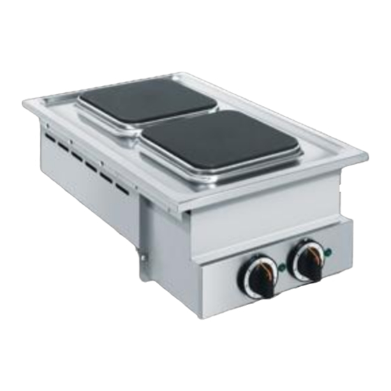
- Page 4 1 - DIAGRAM Fig. 1 I2PQ I2PQ I4PQ I4PQ 11.5 11.5 11.5 11.5 11.5 11.5 11.5 11.5 I2PQ I2PQ I4PQ I4PQ Terminal board Knob Green indicator light (resistance) Cable input Equipotenital Data plate Screw 501_03 - ELECTRIC COOKERS 4 · 19...
- Page 5 1 - DIAGRAM Fig. 2 11.5 11.5 11.5 11.5 11.5 11.5 11.5 11.5 Terminal board Knob Green indicator light (resistance) Cable input Equipotenital Data plate Screw 501_03 - ELECTRIC COOKERS 5 · 19...
-
Page 6: Characteristics Of The Appliances
2 - CHARACTERISTICS OF THE APPLIANCES These appliances are used for professional purposes. Installation, CAT/KAT GAS/GAZ II2H3B/P P mbar repair and use must be carried out by expert personnel. II2H3+ P mbar II2H3+ P mbar The data plate (T) is located on the appliance and contains all the II2L3B/P P mbar data needed for installation. - Page 7 4 - INSTALLATION INSTRUCTIONS 4.1 Safety rules 4.3.2 Statutory regulations and technical requirements During installation of the appliance, the following regulations must • Installation, modifications and maintenance of the appliance be adhered to: must be carried out by authorised personnel in compliance with •...
-
Page 8: Set-Up For Operation
4 - INSTALLATION INSTRUCTIONS The worktable and appliance are clamped with six M5 screws; first Panels and/or inflammable parts must be at a distance of at least drill the relevant holes in the worktable as described in fig. 3. In 300 mm from the hot walls of the machine. - Page 9 CHARACTERISTICS Fig. 3 501_03 - ELECTRIC COOKERS 9 · 19...
- Page 10 CHARACTERISTICS Fig. 4 501_03 - ELECTRIC COOKERS 10 · 19...
- Page 11 CHARACTERISTICS Fig. 5 604 outside 604 outside outside outside 501_03 - ELECTRIC COOKERS 11 · 19...
- Page 12 5 - SET-UP FOR OPERATION 5.3 Ignition Fig. 7 5.3.1 Electricals plates Turn on the main switch upstream of the appliance. Turn the knob (pos. 1 fig. 6) for the plate required to a number between 1 and 6. The green indicator light (pos. 2 fig. 6) come on indicates that the resistances are operational.
-
Page 13: Safety, Cleaning And Repair Rules
6 - INSTRUCTIONS FOR USE 6.1 Safety, cleaning and repair rules 6.3 Appliance care and frequency of maintenance • This appliance is used for the preparation of meals at industri- Attention! When cleaning, carefully avoid washing the al level. Usage and cleaning can be carried only by expert per- appliance with direct water jets or high-pressure sonnel. - Page 14 6 - INSTRUCTIONS FOR USE • contact with non-ferrous metals (element build up) 6.4.3 The 2002/96/EC (WEEE) Directive: • lack of oxygen (i.e. no air inlet, water lacking oxygen). information to users This informational note is meant only for Fig. A owners of equipment marked with the 6.4.2 Warnings and advice for maintenance of stainless symbol shown in fig.
-
Page 15: Appendix: Electrical Diagrams
7 - APPENDIX: ELECTRICAL DIAGRAMS 2600 w 2000 w I2P - 1xR1+1xR2 1800 w 1150 w 1200 w 850 w I2PQ - 2xR1 600 w 300 w 400 w 220 w 270 w 175 w 2 1 3 3 4... - Page 16 7 - APPENDIX: ELECTRICAL DIAGRAMS 2600 w 2000 w I4P - 2 xR1+2xR2 1800 w 1150 w 1200 w 850 w I4PQ - 4 600 w 300 w 400 w 220 w 270 w 175 w 2 1 3 3 4 2 1 3 3 4 R1/R2 R1/R2...
- Page 17 7 - APPENDIX: ELECTRICAL DIAGRAMS Terminal 4a Color cables Blue section 1.5 mm Terminal 4 Color cables White section 1.5 mm Terminal 2 Color cables Red section 1.5 mm Residual heat Color cables Green section 1 mm lamps 50 55 50 55 400 V 3N to P1 of C2...
- Page 18 7 - APPENDIX: ELECTRICAL DIAGRAMS 50 55 50.17 50 55 50.17 400 V 3N Terminal 4a Color cables Blue section 1.5 mm Terminal 4 Color cables White section 1.5 mm Terminal 2 Color cables Red section 1.5 mm to P1 of E1 Residual heat Color cables Green section 1 mm...
- Page 19 IF THE INSTRUCTIONS CONTAINED IN THIS MANUAL ARE NOT OBSERVED. GIGA GRANDI CUCINE S.r.l. - Via Pisana, 336 - Loc. Olmo - 50018 SCANDICCI (FI) - ITALY - Tel. +39 055 722 33 (11 linee r.a.) - Fax +39 055 7310 056 - www.gigagrandicucine.it -...
Need help?
Do you have a question about the I2P and is the answer not in the manual?
Questions and answers